English
- All
- Product Name
- Product Keyword
- Product Model
- Product Summary
- Product Description
- Multi Field Search

Views: 0 Author: Site Editor Publish Time: 2026-10-18 Origin: Site

Can advanced CNC machines achieve precision without the right cutting tools? Tool geometry, wear, and vibration directly affect machining accuracy. Milling Tools help manufacturers maintain tight tolerances, smooth surfaces, and consistent results. This article explores how they improve accuracy across different CNC processes and applications.
Milling Tools influence accuracy through cutting edge geometry, rigidity, wear resistance, and cutting stability.
Their performance varies across different CNC processes. Understanding these differences helps manufacturers select tools for specific machining requirements.
Face milling removes material across broad workpiece surfaces. It commonly prepares mounting faces, machine bases, and assembly interfaces.
Suitable face milling cutters distribute cutting loads across their cutting edges. This helps produce consistent surfaces and reduce machining variation.
However, insert positioning and spindle alignment remain essential. Poor cutter alignment can create uneven surfaces and dimensional errors.
Slot milling creates channels, keyways, and other internal features. These operations require accurate slot dimensions and straight sidewalls.
Suitable end mills help control cutting forces and tool deflection. Their cutting diameter and flute geometry influence finished slot accuracy.
Tool runout can also produce oversized slots. Manufacturers should verify cutter dimensions and toolholding accuracy before machining.
Contour milling creates curved edges, stepped surfaces, and detailed component profiles.
Milling Tools for Complex CNC Parts must maintain stable cutting engagement. Excessive deflection can cause dimensional variation along curved surfaces.
Corner radius and ball nose cutters support different contouring requirements. Their geometry should match the desired component shape.
Pocket milling removes material inside defined component boundaries. It commonly produces cavities, recesses, and internal mechanical features.
Accurate pocket milling requires controlled cutting engagement and suitable toolpaths. Excessive cutting forces may affect wall dimensions and corner accuracy.
Manufacturers should balance material removal rates against finishing requirements.
Three-dimensional milling produces curved surfaces and complex mold geometries.
Ball nose cutters are commonly selected for these applications. Their rounded cutting edges help machine curved surfaces accurately.
Surface finish depends on stepover distance, tool diameter, and cutting conditions.
Smaller stepovers can reduce scallop height but increase machining time.
Micro milling involves producing extremely small features using miniature cutting tools.
These operations demand precise toolholding and carefully controlled cutting parameters. Even minor runout can affect the performance of small cutters.
Micro Machining Tools support detailed cavities, narrow channels, and miniature component profiles.
They are especially valuable when conventional milling cutters cannot access restricted features.
Finish milling removes small amounts of material to achieve final dimensions.
It requires sharp cutting edges, stable toolholding, and consistent cutting engagement.
Suitable finishing cutters reduce surface irregularities and improve dimensional repeatability.
Manufacturers should reserve appropriate finishing allowances after rough machining.
Tip: Match milling cutter geometry to the machining operation before increasing cutting speeds or feed rates.
Different industries require different machining tolerances, materials, and component geometries.
Appropriate milling tools support these requirements by improving process stability and repeatability.
Aerospace machining frequently involves aluminum alloys, titanium, and demanding engineering materials.
Precision milling cutters produce structural profiles, mounting features, and complex component surfaces.
These operations require suitable chip evacuation and controlled cutting forces.
Manufacturers should prioritize dimensional stability when machining thin-walled aerospace components.
Automotive manufacturing depends on repeatable machining across large production batches.
Milling Tools produce engine-related components, transmission housings, mounting surfaces, and precision mechanical features.
Stable cutting performance helps maintain consistent dimensions throughout production.
Longer tool life can also reduce interruptions during automated manufacturing.
Mold manufacturing requires accurate cavities, complex contours, and smooth finished surfaces.
Hardened tool steels present additional challenges involving cutting forces and tool wear.
Suitable carbide cutters provide the rigidity needed for precision machining.
Specialized corner radius and ball nose tools support different cavity geometries.
Medical and precision instrument manufacturing often requires small, accurate component features.
Stainless steel and titanium components demand careful cutting parameter selection.
Miniature milling cutters help produce narrow slots, small profiles, and intricate surfaces.
Accurate machining supports component assembly and consistent finished part quality.
Note: Industry requirements alone cannot determine tool selection. Workpiece materials and component tolerances remain essential factors.
Dimensional accuracy depends on both cutting tool quality and machine setup.
Even well-designed Milling Tools require stable operating conditions to achieve consistent results.
Cutting forces can bend milling cutters during machining.
Excessive deflection causes dimensional variation and uneven component surfaces.
Solid carbide cutters offer high stiffness compared with similar HSS tools.
Their rigidity supports accurate cutting under suitable machining conditions.
Manufacturers should also minimize tool overhang to reduce bending forces.
Cutting edge geometry influences chip formation, cutting forces, and surface quality.
Sharp edges can reduce cutting resistance in suitable materials. Stronger edge preparations may improve durability during demanding operations.
Helix angle also influences how cutting edges engage the workpiece.
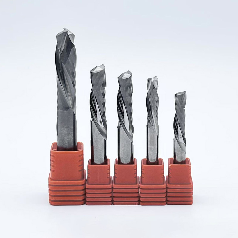
For example, HRC56 Carbide End Mills feature a 35-degree helix design and coated carbide construction.
These features can support cutting stability when matched to suitable materials.
Tool runout occurs when a cutter rotates outside its intended axis.
Excessive runout creates uneven chip loads across cutting edges. This can reduce tool life and affect dimensional accuracy.
Precision collets and suitable toolholders help maintain proper cutter alignment.
Manufacturers should inspect holders regularly and verify runout when accuracy problems occur.
Spindle speed, feed rate, and cutting depth determine cutting conditions.
Excessive cutting engagement can increase deflection and vibration.
Very low feed rates may also cause rubbing rather than effective cutting.
Manufacturers should begin with recommended parameters and make controlled adjustments.
Repeatable machining requires stable cutting conditions throughout production.
Tip: Measure tool runout and verify cutting parameters before adjusting CNC toolpath compensation.
Milling cutter geometry determines how cutting edges contact the workpiece.
Different geometries offer advantages for specific machining operations and surface requirements.
Flute count influences chip clearance, cutting engagement, and feed capability.
Two-flute end mills provide larger chip spaces for many aluminum applications.
Four-flute cutters are commonly selected for steel milling and contour finishing.
Additional flutes may support productive finishing when chip evacuation remains effective.
However, more cutting edges do not automatically improve accuracy.
Helix angle influences cutting force direction and chip movement.
Suitable helix designs can promote smooth cutting engagement and reduce vibration.
Different workpiece materials may require different helix angles.
Manufacturers should consider material behavior and tool rigidity when selecting cutters.
Different cutter profiles serve different machining requirements.
Square end mills produce flat-bottom features and straight sidewalls.
Ball nose cutters machine curved surfaces and complex three-dimensional profiles.
Corner radius cutters strengthen vulnerable cutting corners during suitable operations.
Milling Tool Type | Typical CNC Operation | Accuracy Consideration |
|---|---|---|
Square End Mill | Slots and flat-bottom pockets | Slot width and wall straightness |
Ball Nose End Mill | 3D surfaces and curved contours | Surface scallop height |
Corner Radius End Mill | Contouring and profile milling | Edge stability and corner geometry |
Micro End Mill | Miniature features and small cavities | Runout and tool deflection |
Face Milling Cutter | Broad flat surfaces | Insert positioning and surface flatness |
Tool dimensions influence cutting stiffness and feature accessibility.
Longer cutters can reach deeper cavities but experience greater deflection.
Larger diameters generally provide more rigidity under similar operating conditions.
However, component geometry may require smaller cutting diameters.
Manufacturers should select the shortest practical cutter for each operation.
Tip: Choose cutter geometry according to the finished feature rather than using one tool design for every CNC operation.
Cutting tool materials determine stiffness, wear resistance, and thermal performance.
Their selection becomes especially important during demanding precision machining operations.
Solid carbide offers high hardness and stiffness for demanding cutting applications.
It helps cutting edges resist abrasive wear during repeated machining operations.
These properties support consistent dimensions when cutting parameters remain suitable.
Manufacturers can explore Precision Milling Tools for different CNC manufacturing requirements.
Tool selection should consider material hardness, cutter geometry, and machining conditions.
Protective coatings help reduce cutting edge wear under suitable conditions.
TiAlN and AlTiN coatings are commonly used for demanding steel machining.
They can improve thermal performance and cutting edge durability.
However, coating selection depends on material type and cooling conditions.
An unsuitable coating may increase friction or encourage material adhesion.
Aluminum and other non-ferrous materials often produce long, adhesive chips.
Polished cutting edges can reduce material buildup during machining.
Uncoated or specially coated tools may perform better in these applications.
Suitable flute geometry helps maintain effective chip evacuation.
Manufacturers should evaluate material adhesion before selecting a coating.
Tool wear gradually changes cutting edge geometry.
This can increase cutting forces and affect finished component dimensions.
Wear-resistant Milling Tools help maintain more consistent cutting performance.
However, manufacturers still need regular inspection and replacement procedures.
Tool life should be evaluated against actual dimensional tolerance requirements.
Note: Tool hardness alone does not guarantee better accuracy. Cutting geometry, workpiece material, and machine stability also influence results.
Accuracy problems often develop from tool wear, unstable setups, and unsuitable cutting parameters.
Identifying their causes helps manufacturers reduce defects and improve machining consistency.
Chatter creates unwanted vibration between the cutter and workpiece.
It can produce visible surface marks and dimensional variation.
Excessive tool overhang, poor workholding, and unsuitable cutting conditions increase chatter risk.
Manufacturers should improve setup rigidity before increasing cutting speed.
Burrs form when material deforms near the cutting edge.
Their formation depends on material properties, tool geometry, and cutting direction.
Worn cutters may increase burr formation and surface roughness.
Suitable edge preparation and finishing strategies help improve component quality.
Chip accumulation creates additional cutting resistance and heat.
Recycled chips may damage finished surfaces or accelerate tool wear.
Deep pockets and narrow slots are especially vulnerable to chip buildup.
Appropriate flute geometry and chip removal strategies improve cutting reliability.
Tool wear changes the effective cutting edge position.
This can produce gradual dimensional changes across production batches.
Manufacturers should monitor tool condition and finished component measurements.
Wear compensation may help maintain dimensions within acceptable limits.
However, damaged cutters must be replaced before tool failure occurs.
Tip: Record recurring machining defects alongside tool condition, cutting parameters, and machine setup information.
Selecting suitable Milling Tools requires careful evaluation of component requirements.
Manufacturers should compare cutting performance rather than relying only on tool specifications.
Start by reviewing the component drawing and required machining features.
Identify critical dimensions, surface finish requirements, and geometric tolerances.
These requirements determine the necessary cutter diameter and cutting geometry.
Tighter tolerances may require dedicated finishing tools and stable machining setups.
Different CNC processes require different cutting tool geometries.
Face milling cutters support broad surface machining.
Square end mills suit slots, pockets, and straight profiles.
Ball nose tools support complex three-dimensional surfaces.
Micro milling cutters address small features and restricted machining areas.
Workpiece hardness, toughness, and chip formation influence tool selection.
Machine rigidity and spindle accuracy also affect achievable precision.
A high-performance cutter cannot compensate for an unstable machining setup.
Manufacturers should verify machine capabilities before selecting demanding cutting parameters.
Machining trials provide practical evidence of tool performance.
Manufacturers should measure finished dimensions, surface quality, and tool wear.
They should also monitor machining time and process stability.
A simple trial comparison can support informed purchasing decisions.
Evaluation Factor | Recommended Assessment |
|---|---|
Dimensional Accuracy | Measure critical component dimensions |
Surface Quality | Check roughness and visible defects |
Tool Wear | Inspect cutting edges after machining |
Process Stability | Monitor vibration and machining consistency |
Production Efficiency | Compare cycle times and tool changes |
Tip: Test candidate cutters under identical conditions before selecting tools for large production orders.
Milling Tools improve CNC machining accuracy through suitable cutting geometry, rigidity, and wear resistance. They help maintain tight tolerances, smooth surfaces, and consistent results across different machining processes.
Proper tool selection and cutting parameters further improve production efficiency and reduce machining errors.
SUPSTEED PRECISION TOOLS provides precision carbide milling tools for demanding CNC applications. Its cutting solutions support reliable machining performance, improved productivity, and consistent component quality.
A: Milling Tools remove material to create accurate surfaces, slots, and contours.
A: Milling Tools reduce deflection and support precise cutting when properly selected.
A: They improve surface finish, consistency, and cutting stability.
A: Durable cutters reduce tool changes and machining waste.
A: Ball nose cutters suit curved surfaces; square end mills suit flat features.
A: Tool wear, runout, and vibration commonly reduce accuracy.