English
- All
- Product Name
- Product Keyword
- Product Model
- Product Summary
- Product Description
- Multi Field Search

Views: 0 Author: Site Editor Publish Time: 2026-10-19 Origin: Site

Can precision drilling deliver accurate holes without the right cutting tools? Runout, vibration, and chip buildup often cause dimensional errors. Holemaking Tools improve drilling stability, hole accuracy, and surface quality. This article explores how drill geometry, carbide materials, and machining techniques help manufacturers achieve consistent precision.
Precision drilling involves more than creating holes in metal components. Manufacturers must control diameter, position, roundness, and surface quality.
Holemaking Tools for Precision Drilling address these requirements through suitable cutting geometry and stable machining performance.
Drill point geometry determines how a cutter enters the workpiece. Poor initial engagement can cause the tool to move away from its intended position.
A properly designed drill point helps distribute cutting forces more evenly. Cutting lip symmetry and suitable point geometry improve initial drilling stability.
Split-point designs can also reduce wandering in suitable materials. However, drill entry conditions and machine alignment remain important.
Drill deflection occurs when cutting forces bend the tool during machining. Excessive deflection can produce positional errors and poor hole straightness.
Solid Carbide Drills offer high stiffness compared with similar HSS drills. Their rigidity helps maintain a more stable cutting path.
Shorter drill lengths generally provide better resistance to bending. Manufacturers should avoid unnecessary tool overhang whenever possible.
Cutting edge geometry directly affects finished hole dimensions.
Unequal cutting lips can generate unbalanced forces during drilling. This may increase hole diameter variation and accelerate tool wear.
Precisely manufactured cutting edges help maintain balanced cutting engagement. Their consistency supports more repeatable hole sizes during CNC production.
Roundness describes how closely a hole's cross-section approaches a perfect circle.
Vibration and uneven cutting forces can produce irregular hole shapes. Excessive runout may also increase dimensional variation.
Properly selected Holemaking Tools support stable cutting engagement. However, workholding and spindle condition also influence final roundness.
Drilling produces chips inside a confined cutting area.
If chips remain inside the hole, they can scratch its walls. They may also increase friction, heat, and cutting resistance.
Suitable flute geometry helps move chips away from the cutting edges. Coolant delivery further supports chip evacuation under appropriate conditions.
Cutting edges gradually wear during repeated drilling operations.
This wear changes cutting geometry and can influence hole dimensions. It may also increase cutting forces and reduce surface quality.
Wear-resistant carbide substrates help maintain cutting edge performance. Appropriate coatings provide additional protection during demanding machining.
Manufacturers should monitor tool wear before finished holes exceed tolerance limits.
Tool runout causes cutting edges to rotate unevenly around the spindle axis.
Excessive runout creates unequal cutting loads and inconsistent hole geometry.
Precision toolholders help maintain proper drill alignment. Collet condition, spindle accuracy, and correct tool installation also matter.
Tip: Measure tool runout before changing cutting parameters when hole diameter or position becomes inconsistent.
Drill geometry controls cutting engagement, chip formation, and tool guidance.
Selecting the correct geometry helps manufacturers improve dimensional accuracy across different materials and drilling operations.
Common drill point angles include 118°, 135°, and 140°.
A 118° point is widely associated with general-purpose drilling. A 135° split point often improves centering on suitable materials.
However, point angle alone cannot determine drilling accuracy.
Cutting lip symmetry, chisel edge design, and workpiece conditions also affect performance.
Cutting lips should engage the workpiece as evenly as possible.
Unequal lip lengths or cutting angles create unbalanced cutting forces. These forces can increase vibration and produce inaccurate holes.
Precision grinding helps maintain consistent cutting edge geometry.
Manufacturers should inspect worn or damaged drills when hole dimensions begin changing.
Drill flutes provide channels for removing material during cutting.
Their shape influences chip formation, flow, and available clearance.
Steel, aluminum, and stainless steel produce different chip characteristics. Therefore, flute geometry should match workpiece material and drilling depth.
Poor chip evacuation can damage hole surfaces and shorten tool life.
Drill margins provide guidance along the hole wall during drilling.
Suitable margin geometry helps maintain stable tool movement inside the hole.
However, excessive contact can increase friction and heat.
Effective drill designs balance hole guidance, cutting stability, and surface protection.
Note: Drill geometry affects hole quality, but machine accuracy and workpiece stability remain equally important.
Solid carbide cutting tools are widely used in demanding CNC drilling applications.
Their hardness, rigidity, and wear resistance support stable machining under suitable operating conditions.
Solid carbide provides greater stiffness than conventional high speed steel.
This property helps reduce drill deflection during stable machining.
Its high hardness also supports cutting edge durability under demanding conditions.
However, carbide is relatively brittle compared with HSS. Severe vibration or interrupted cutting can cause edge damage.
Manufacturers should use rigid machines and suitable toolholding systems.
Protective coatings can reduce wear during precision drilling operations.
TiSiN and TiAlN coatings are used in selected demanding machining applications. Their suitability depends on workpiece materials and cutting conditions.
Coatings help protect cutting edges against specific wear mechanisms.
However, selecting the wrong coating may increase friction or material adhesion.
Manufacturers should follow application-specific coating recommendations.
Carbide drills are available in different length-to-diameter configurations.
Common options include 3D, 5D, and 8D designs.
These designations describe drilling depth relative to tool diameter.
For example, a 5D drill supports a nominal depth-to-diameter ratio of five.
Longer drills require greater attention to chip evacuation and cutting stability.
Steel drilling requires suitable cutting geometry and wear resistance.
Carbon steel, alloy steel, and stainless steel present different machining challenges.
Some materials produce tough chips or significant cutting heat.
Solid Carbide Drills for Precision Machining help address these conditions through suitable substrate and flute designs.
Manufacturers can review Holemaking Tools for CNC Machining when comparing drilling applications.
Tip: Choose carbide drills according to material hardness, hole depth, and machine capability rather than cutting speed alone.
Different holemaking operations require different cutting tools.
Drilling creates the initial hole, while finishing operations improve selected dimensions and surfaces.
Twist drills are commonly used for general holemaking operations.
They provide a practical solution for many standard drilling requirements.
Solid carbide drills offer greater rigidity and wear resistance under suitable conditions. They are often selected for productive CNC drilling applications.
Tool selection should consider workpiece material, drilling depth, and required tolerance.
Spot drills prepare a controlled entry location before drilling.
They are useful when initial positioning presents machining challenges.
A suitable pilot or spotting operation can help improve drill entry stability.
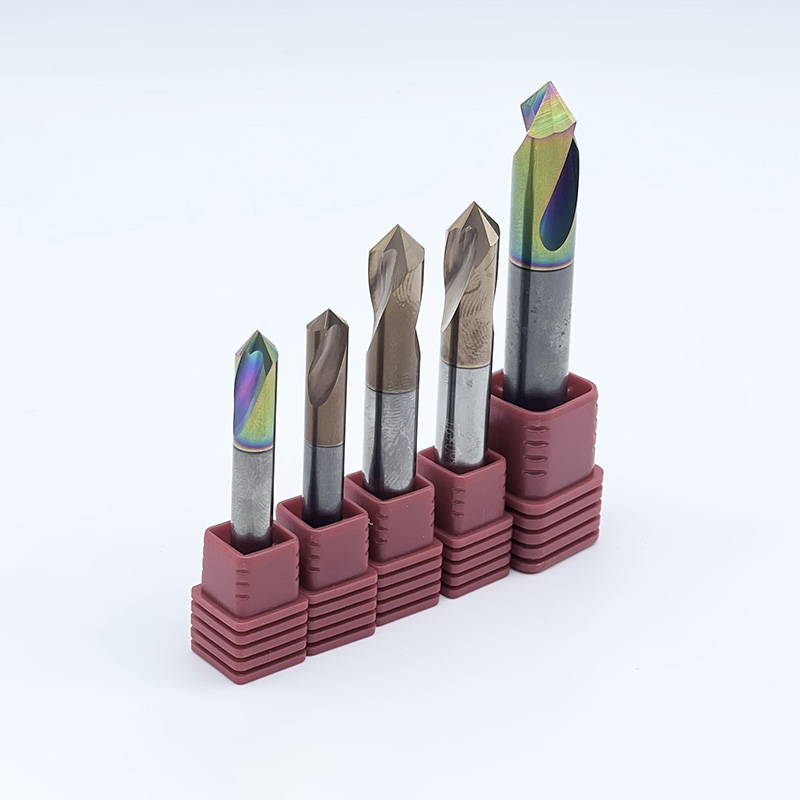
Manufacturers can consider Pilot Drills for appropriate hole-starting operations.
However, some self-centering carbide drills can operate without separate spotting.
Reaming removes a small finishing allowance from an existing hole.
It improves diameter consistency and can produce smoother hole surfaces.
Precision Reamers are useful when drilling alone cannot achieve the required finish.
For example, Reamers support hole-finishing operations requiring controlled dimensions.
However, reamers generally follow the existing hole path. They cannot reliably correct significant positional errors.
Boring tools enlarge and refine previously machined holes.
They can improve diameter accuracy and correct certain alignment problems.
Unlike reaming, boring uses a controlled cutting path to remove material.
It is suitable when hole position or geometry requires correction.
Manufacturers should select boring or reaming according to the actual dimensional problem.
Holemaking Tool | Main Function | Accuracy Benefit |
|---|---|---|
Twist Drill | Create initial holes | General hole production |
Solid Carbide Drill | Precision CNC drilling | Improved cutting stability |
Spot or Pilot Drill | Prepare hole entry | Better starting control |
Reamer | Finish existing holes | Improved diameter and surface quality |
Boring Tool | Refine hole geometry | Improved alignment and diameter control |
Tip: Use drilling for hole creation, reaming for suitable finishing requirements, and boring when geometry correction is necessary.
Hole depth directly influences drilling stability and chip evacuation.
Longer drills are generally more sensitive to deflection and cutting disturbances.
Choosing the correct drill length helps maintain reliable machining performance.
Short-hole drilling generally provides better tool rigidity.
A 3D drill is designed for a nominal drilling depth around three times its diameter.
Its shorter working length helps reduce unnecessary bending.
These drills are suitable for many shallow-hole CNC applications.
Manufacturers should still verify point geometry, runout, and cutting parameters.
A 5D drill provides greater cutting reach than shorter designs.
However, additional length can increase drilling instability.
Suitable flute geometry helps remove chips during deeper cutting operations.
Manufacturers should maintain stable toolholding and appropriate feed rates.
Cooling requirements also become more important as drilling depth increases.
An 8D drill supports deeper machining relative to its diameter.
These operations require careful control of hole straightness and chip removal.
Excessive cutting forces may cause deflection or premature tool failure.
Some drill designs benefit from pilot holes and through-tool coolant systems.
Manufacturers should confirm the recommended entry procedure before machining.
Coolant helps manage cutting temperatures and remove chips.
External coolant works well in some shallow drilling applications.
Through-tool coolant can provide more direct delivery to deeper cutting zones.
For demanding applications, Carbide Drills and Coolant Fed Drills provide relevant tooling options.
However, coolant pressure and flow must match the drill design.
Tip: For deeper holes, prioritize chip evacuation, tool guidance, and coolant delivery before increasing cutting speeds.
Even high-quality Holemaking Tools can produce inaccurate holes under unsuitable conditions.
Understanding common defects helps manufacturers identify the correct process adjustments.
Excessive tool runout can produce holes larger than the intended diameter.
It creates uneven cutting loads across the drill lips.
Manufacturers should inspect the spindle, toolholder, and cutting edges.
Correcting alignment problems may improve hole dimensions without replacing the drill design.
Hole wandering occurs when a drill moves away from its intended cutting path.
Inclined surfaces, unstable clamping, and unsuitable entry geometry increase this risk.
Pilot drilling or controlled entry strategies may improve stability.
However, the best solution depends on drill design and workpiece conditions.
Poor surface quality often results from worn cutting edges or unsuitable parameters.
Chip recutting may also scratch internal hole surfaces.
Burrs can develop around hole entrances and exits.
Manufacturers should inspect tool wear and adjust cutting conditions.
Suitable finishing operations may improve the final hole quality.
Drill breakage can result from excessive feed rates or chip accumulation.
Insufficient coolant and unstable toolholding also increase failure risks.
Manufacturers should check cutting loads and chip evacuation before replacing damaged tools.
Stable machining conditions help extend effective tool life.
Note: Repeated drilling defects often indicate process problems rather than unsuitable tool materials alone.
Selecting precision drilling tools requires a clear understanding of component requirements.
Manufacturers should evaluate finished hole quality rather than relying only on tool specifications.
Start by reviewing engineering drawings and critical dimensions.
Identify hole diameter, positional tolerance, roundness, and surface requirements.
These specifications determine whether drilling alone is sufficient.
Tighter tolerances may require additional boring or reaming operations.
Manufacturers should distinguish hole position from diameter accuracy during inspection.
Workpiece properties influence tool selection and cutting performance.
Hard materials may require wear-resistant carbide grades and suitable coatings.
Materials producing long chips require effective flute geometry.
Drill point design should support stable entry conditions.
Manufacturers should select tools according to actual machining requirements.
Machine stability directly affects achievable drilling precision.
Spindle alignment, toolholding condition, and workpiece clamping require inspection.
Cutting speed and feed rate must match drill capabilities.
Coolant delivery should support chip evacuation and heat management.
Manufacturers should document successful cutting conditions for future production.
Machining trials help verify whether selected tools meet production requirements.
Manufacturers should measure hole dimensions and inspect surface quality.
They should also monitor cutting edge wear and process stability.
Repeatable results across multiple parts provide stronger evidence of reliable performance.
Inspection Factor | Recommended Evaluation |
|---|---|
Hole Diameter | Measure actual diameter against specified tolerance |
Hole Position | Verify location against drawing datums |
Roundness | Inspect geometric consistency |
Hole Straightness | Check deviation along drilling depth |
Surface Finish | Evaluate roughness and visible defects |
Tool Wear | Inspect cutting edges during production |
Tip: Establish measurable acceptance criteria before approving Holemaking Tools for recurring precision drilling operations.
Holemaking Tools improve precision drilling through accurate cutting geometry, rigidity, and effective chip evacuation. They help maintain consistent hole dimensions, positioning, and surface quality.
Proper carbide grades, coatings, and drilling parameters further enhance tool life and machining stability.
SUPSTEED PRECISION TOOLS provides carbide drills, pilot drills, and precision reamers for CNC applications. Its cutting solutions help manufacturers achieve reliable hole quality, higher productivity, and consistent machining results.
A: Holemaking Tools include drills, reamers, and boring cutters for accurate holes.
A: Holemaking Tools improve hole positioning, diameter consistency, and cutting stability.
A: They offer high rigidity, wear resistance, and consistent cutting performance.
A: Costs depend on carbide grade, coatings, geometry, and hole depth.
A: Reamers improve diameter accuracy and surface finish after drilling.
A: Excessive runout, worn edges, and vibration can cause oversizing.