English
- All
- Product Name
- Product Keyword
- Product Model
- Product Summary
- Product Description
- Multi Field Search

Views: 0 Author: Site Editor Publish Time: 2026-08-20 Origin: Site

Machining hardened steel between HRC 50 and 68 is an unforgiving and highly technical process. A single tool failure can scrap a high-value mold, die, or critical aerospace component in a fraction of a second. Standard end mills lack the rigidity, specialized geometry, and extreme thermal resistance required for this demanding environment. Using conventional cutters on hardened alloys inevitably leads to catastrophic tool breakage, poor surface finishes, and unpredictable production metrics. Selecting the correct tooling requires a rigorous evaluation of actual material hardness, advanced tool geometry, high-performance coatings, and machine-side rigidity. We will explore the comprehensive framework for evaluating and shortlisting hard milling end mills to ensure process stability, dimensional accuracy, and long-term profitability on the shop floor.
Relying on broad material classifications like D2, H13, or 4140 is entirely insufficient for accurate tool selection. The exact same block of mold steel can vary wildly in hardness depending on its specific heat treatment, tempering process, and quenching method. You must verify the exact post-heat-treat Rockwell Hardness (HRC) before finalizing your tool selection. A block of H13 might measure HRC 45 in an annealed or pre-hardened state, yet reach HRC 54 after a full vacuum hardening cycle. Treating these two states identically guarantees premature tool wear or sudden breakage.
Machinists must measure the actual hardness of the workpiece using calibrated testing equipment before loading tools into the magazine. Only then can you match the carbide substrate and edge geometry to the physical reality of the metal. Implementing a strict hardness verification protocol prevents costly assumptions.
Cutting hardened alloys presents severe mechanical and thermal challenges. You face immense cutting forces, extreme heat generation at the shear zone, and rapid edge wear caused by abrasion. Deflection is the silent killer in these operations. It pushes the tool away from the cut, altering critical dimensions and placing immense stress on the brittle carbide substrate. When a tool deflects, the clearance angle changes, causing the heel of the cutting edge to rub against the workpiece rather than shear it. This rubbing generates excessive friction and work-hardens the material surface, making the next cutter pass even more difficult.
Success requires predictable tool life and strict dimensional accuracy across the entire part. Achieving these criteria eliminates the need for slow, secondary EDM or manual grinding operations. By controlling deflection and managing tool wear, you save significant production time and maintain the tight tolerances required in modern mold making. You must evaluate the entire machining setup to eliminate weak points that contribute to tool bending.
Deflection Impact on Hardened Steel Machining
| Deflection Severity | Immediate Physical Result | Impact on Workpiece | Impact on Tool Life |
|---|---|---|---|
| Minor (0.0001" - 0.0005") | Slight chatter, uneven chip load | Visible witness marks, loss of mirror finish | Premature edge wear, micro-chipping |
| Moderate (0.0005" - 0.0015") | Heavy vibration, loud harmonics | Dimensional inaccuracy, surface work-hardening | Flute snapping, rapid coating degradation |
| Severe (> 0.0015") | Tool bending beyond elastic limit | Scrapped part, gouged surfaces | Catastrophic tool breakage at the shank |
Traditional 4-flute designs work adequately for standard profiling and roughing in softer materials. However, finishing operations in hardened steel demand high-flute-count tools. Transitioning to 5, 6, or even 8-flute end mills is required for finishing passes. More flutes significantly decrease the chip load per tooth while allowing the spindle to maintain high feed rates. This distribution of cutting forces prevents tool overload and minimizes vibration.
The mathematics of milling dictate that Feed Rate equals RPM multiplied by the number of flutes and the chip load per tooth. Because hardened steel restricts your maximum RPM due to heat generation, the only effective way to increase your feed rate without overloading the cutting edge is to add more flutes. Consequently, high-flute cutters achieve the mirror-like surface finishes required for injection molds and precision stamping dies, reducing the need for hand polishing. They provide continuous engagement, ensuring the tool does not bounce in and out of the cut.
Tool rigidity dictates success or failure in hard milling. Follow a strict rule of thumb for flute length: select an end mill with a flute length that is the same, or only slightly longer, than the slot's or profile's maximum depth of cut. Stub-length tools and tapered core webs are critical elements of tool geometry. They maximize tool rigidity and minimize deflection under heavy radial loads. The Length-to-Diameter (L/D) ratio should ideally be kept under 3:1 for hard milling applications. If you double the stick-out length of an end mill, its deflection increases by a factor of eight.
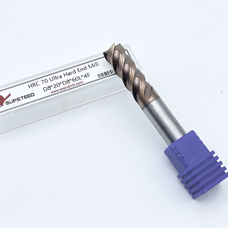
A thick core web resists the bending forces inherent in high-hardness machining. Standard end mills typically feature a core diameter that is roughly 50% of the tool's outer diameter. In contrast, tools designed for hardened steel utilize a core diameter of 65% to 70%. This massive increase in cross-sectional area provides the stiffness required to push through HRC 60+ materials. When a tool bends, even microscopically, it causes chatter, chips the cutting edge, and ruins the workpiece surface.
Sharp-edged end mills risk immediate chipped corners when engaging hardened steel. The cutting forces concentrate on the weakest point of the tool. We highly recommend corner radius geometries to distribute cutting forces evenly and prolong tool life. A radius strengthens the cutting edge, allowing it to withstand the initial shock of entering the cut. Manufacturers also apply a microscopic edge hone—often measuring just 0.001 to 0.002 inches—to slightly dull the absolute peak of the cutting edge. This hone directs the cutting forces away from the fragile tip and into the robust carbide body.
When handling complex 3D profiling in mold making, ball nose end mills require careful attention. The ball joint precision must strictly match the required machining accuracy of the high-hardness mold. Any deviation in the ball profile will leave witness marks on the part, necessitating costly rework. The transition from the radius of the ball to the straight flute must be perfectly tangential. Even a 0.0005-inch mismatch at this joint will drag against the hardened steel, causing friction and destroying the surface finish.
Industry-standard coatings for hard milling include Aluminum Titanium Nitride (AlTiN), Titanium Aluminum Nitride (TiAlN), and Titanium Silicon Nitride (TiSiN). These advanced coatings excel in high-heat environments where uncoated carbide would rapidly degrade. They function by forming a protective aluminum oxide layer when exposed to high cutting temperatures at the shear zone. This microscopic, ceramic-like barrier shields the raw carbide substrate from thermal degradation, oxidation, and severe abrasive wear.
The coating also provides a lower coefficient of friction, allowing chips to evacuate smoothly without welding to the cutting flutes. TiSiN coatings are particularly effective for extreme hardness. The addition of silicon creates a nanocomposite structure that can withstand oxidation temperatures exceeding 1100°C. This allows the heat generated by the cutting action to be transferred into the chip rather than absorbed by the tool body. Keeping the carbide substrate cool is the primary function of these high-performance coatings.
A common and destructive misconception is that liquid coolant helps in hard milling. In reality, liquid coolant causes severe thermal shock. This phenomenon leads to micro-fracturing of the carbide edge as the tool rapidly heats in the cut and cools instantly outside it. Carbide expands slightly under the intense heat of the shear zone. When a blast of cold liquid coolant hits that expanded edge, it contracts violently, creating microscopic cracks parallel to the flute. Within minutes, these cracks propagate, and the cutting edge crumbles.
Dry cutting with a high-pressure air blast is the required standard for hardened materials. Air clears chips effectively without shocking the tool. You must configure dual air nozzles aimed directly at the cutting zone to ensure chips are evacuated instantly. Recutting a hardened steel chip will destroy an end mill faster than any other variable. However, dry cutting only works if the end mill and coating are explicitly designed for it. Basic 4-flute end mills meant for mild steel lack the necessary thermal barriers and will fail rapidly without coolant.
This entry-level hard milling range requires sub-micrograin carbide end mills. The substrate must balance toughness to resist shock and wear resistance to hold an edge. Standard carbide grades will chip easily at HRC 55 due to the increased shear strength of the material. Tools in this category typically utilize a carbide substrate with a grain size of 0.8 to 1.0 microns and a cobalt binder content of around 10%. The cobalt provides the necessary toughness to absorb vibrations during roughing passes.
Ensure the tool features a robust coating like AlTiN to handle the moderate heat generation. At this hardness, you can still achieve reasonable material removal rates, provided the tool geometry supports aggressive roughing without deflecting. You can utilize dynamic milling toolpaths with moderate step-overs, relying on the toughness of the 10% cobalt substrate to handle the radial engagement.
Machining at this elevated level demands highly specific geometric and metallurgical requirements. You must utilize HRC 60 end mills crafted from ultra-fine micrograin carbide. This specialized material maintains edge integrity without sacrificing toughness under extreme cutting forces. The grain size drops to 0.4 to 0.6 microns, and the cobalt content is reduced to approximately 8%. Less cobalt means a harder, more wear-resistant tool, but it also makes the cutter more brittle, demanding a highly rigid machine setup.
The geometry often includes a heavier core, a specialized edge hone, and a negative rake angle to prevent micro-chipping. The edge hone slightly dulls the sharp cutting edge, creating a microscopic radius that absorbs impact and directs cutting forces into the strongest part of the tool body. You cannot plunge these tools directly into the material; you must use helical interpolation or ramp-in strategies at shallow angles (1 to 2 degrees) to protect the bottom cutting edges.
The upper limits of hard milling require highly specialized, application-specific tooling. Standard geometries fail instantly in this zone. Tools designed for HRC 65+ materials utilize pronounced negative rake angles (often -5 to -10 degrees) to direct cutting forces squarely into the thickest part of the carbide substrate. This puts the carbide in a state of compression, which is where the material exhibits its highest mechanical strength.
They also feature specialized, heavy edge hones and advanced nano-composite coatings like TiSiN to withstand extreme abrasion and localized heat. The carbide substrate is typically a nano-grain structure (under 0.4 microns) with very low cobalt content (around 6%). Machining at this hardness is primarily about finishing and semi-finishing, utilizing light depths of cut and high feed rates to peel away material without overloading the spindle. You are essentially grinding with an end mill at this stage, relying on high surface footage and minimal chip loads.
Transitioning from mild steel to hardened alloys requires a complete mindset shift on the shop floor. Never use standard feeds, speeds, or basic tooling when approaching hardened blocks. Attempting to force standard end mills through hardened material will result in immediate tool breakage. Worse, the sudden spike in spindle load can cause severe damage to the machine's bearings and drive systems.
Always recalculate your cutting parameters based on the specific HRC rating, utilizing data provided by the tool manufacturer specifically for hard milling applications. Hard milling requires high surface footage (SFM) to generate enough heat to plasticize the metal at the shear zone, combined with very low chip loads (IPT) to protect the cutting edge. Operators used to cutting aluminum or mild steel often run the RPM too low and the feed too high, which snaps hard milling tools instantly.
Even the most advanced hard milling tools will fail prematurely if spindle runout exceeds acceptable limits. Runout must typically remain under 0.0002 inches for hard milling. If runout exceeds this, one flute takes the majority of the chip load, causing it to wear rapidly and eventually snap. Standard ER collets often lack the gripping force, rigidity, and concentricity needed for high-hardness applications. They consist of multiple moving parts that introduce tolerance stacking.
Contrast this with shrink-fit holders, hydraulic chucks, or precision milling chucks. These advanced tool holding solutions provide the extreme rigidity required to prevent tool pullout, eliminate chatter, and ensure that every flute carries an equal chip load during the cut. Shrink-fit holders, which use thermal expansion and contraction to grip the tool shank directly, offer the lowest possible runout and the highest gripping torque, making them the industry standard for hard milling.
Tool Holder Comparison for Hard Milling
| Holder Type | Typical Runout at 3xD | Gripping Force | Suitability for Hard Milling |
|---|---|---|---|
| Standard ER Collet | 0.0005" - 0.0010" | Low to Medium | Not Recommended |
| Precision Milling Chuck | 0.0002" - 0.0004" | Very High | Acceptable for Roughing |
| Hydraulic Chuck | 0.0001" - 0.0002" | High (Excellent Damping) | Highly Recommended |
| Shrink Fit Holder | < 0.0001" | Maximum | Industry Standard |
Tool survival depends heavily on machine tool rigidity and vibration damping. A lightweight machine lacking mass will struggle to push cutters through HRC 60 steel smoothly, resulting in harmonic vibrations that destroy carbide edges. Machines with polymer concrete bases or heavy cast-iron box ways dampen these vibrations far better than lighter linear-guide machines.
Furthermore, modern CAM strategies are absolutely essential. Constant-engagement toolpaths, such as trochoidal milling or dynamic milling, prevent tool overload in tight corners. They maintain a consistent chip load and cutting angle, drastically extending tool life and allowing for deeper axial cuts even in extremely hard materials. You must utilize radial chip thinning calculations in your CAM software to ensure the actual chip thickness matches the tool manufacturer's recommendations, especially when taking light radial step-overs.
Evaluating tool cost requires analyzing the cost-per-part, rather than just looking at the upfront purchase price. Premium, application-specific end mills often yield a significantly higher return on investment. They deliver extended tool life, predictable wear patterns, and drastically reduce machine downtime caused by tool changes. When machining a $10,000 mold cavity, the reliability of the cutter is paramount.
Budget alternatives might seem appealing initially. However, frequent tool changes, scrapped high-value parts, and poor surface finishes requiring manual rework quickly erase any perceived upfront savings. If a cheap tool breaks mid-cut and gouges the workpiece, the cost of the scrapped block and lost machining time dwarfs the price difference of the premium tool. Investing in the right tool for the specific hardness rating ensures a stable, unattended machining process where operators can trust the tool to complete the cycle without intervention.
Audit your current tool holding setup immediately to eliminate runout and replace standard ER collets with shrink-fit or hydraulic holders. Implement a strict shop-floor protocol to verify the actual Rockwell Hardness of every workpiece before selecting your cutting tools. Update your CAM templates to utilize constant-engagement toolpaths and radial chip thinning calculations specifically tailored for hardened alloys. Standardize your machine setups to include high-pressure, dual-nozzle air blasts, completely removing liquid coolant from your hard milling operations. Run controlled baseline tests on scrap hardened material to validate your speeds, feeds, and toolpath strategies before executing programs on production parts.
A: No. While basic 4-flute end mills cut mild steel effectively, they lack the thick core strength, specialized edge preparation, and high-heat coatings required for hardened steel. Using them results in rapid edge chipping, severe deflection, and catastrophic tool failure.
A: Liquid coolant causes rapid temperature fluctuations at the cutting edge during hard milling. This leads to thermal cracking and micro-fracturing of the carbide. Dry cutting with a high-pressure air blast evacuates chips safely, relying on specialized high-heat coatings to manage cutting temperatures.
A: Tools for HRC 60 require ultra-fine micrograin carbide to withstand extreme cutting forces without sacrificing toughness. They feature thicker core webs, specialized edge hones to prevent micro-chipping, and more advanced nano-composite coatings compared to tools designed for the softer HRC 55 range.
A: A thicker core web significantly increases the structural rigidity of the end mill. This added mass resists the intense bending forces generated when machining hardened steel, minimizing deflection, preventing chatter, and ensuring accurate dimensional tolerances on the final part.
A: For optimal tool life in hard milling, spindle and tool holder runout should be kept below 0.0002 inches. Excessive runout causes uneven chip loads, forcing a single flute to do most of the cutting, which leads to rapid, premature edge failure.
A: Higher flute counts decrease the chip load per tooth. This allows you to maintain high feed rates while taking very light radial cuts. The result is a highly stable cutting process that produces the mirror-like surface finishes required for precision molds and dies.