- All
- Product Name
- Product Keyword
- Product Model
- Product Summary
- Product Description
- Multi Field Search

Views: 0 Author: Site Editor Publish Time: 2026-08-22 Origin: Site

Milling physics relies on a strict inverse relationship. You must balance a tool's core diameter against its flute valley volume. A thicker core provides massive rigidity. A larger valley offers necessary chip evacuation capacity. Getting this balance wrong carries heavy consequences on the shop floor. Tool deflection causes out-of-tolerance parts and tapered walls. Chatter ruins surface finishes and destroys spindle bearings. Chip packing leads to catastrophic tool failure and expensive spindle downtime. To solve these machining issues, operators rely on the 4 flute end mill as the industry-standard baseline for ferrous machining. This specific geometry offers the optimal balance of structural strength, chip clearance, and maximum material removal rate (MRR). This technical guide evaluates exactly when and how to deploy this tooling geometry to optimize your machining operations.
Structural Compromise: A 4 flute design provides a larger core than 2- or 3-flute tools, exponentially increasing rigidity while retaining just enough gullet space for manageable chip evacuation in harder materials.
Cutting Stability & Load Distribution: More flutes mean more edges engaged in the material simultaneously, distributing cutting forces and reducing the per-tooth chip load for smoother, more stable operation.
Material Specificity: It is the default choice for steels and tough alloys, but presents severe chip-packing risks in gummy materials like aluminum unless specific toolpaths are utilized.
Surface Finish vs. Feed Rate: The addition of cutting edges allows for higher feed rates at the same chip load compared to lower flute counts, directly improving surface finish and cycle times.
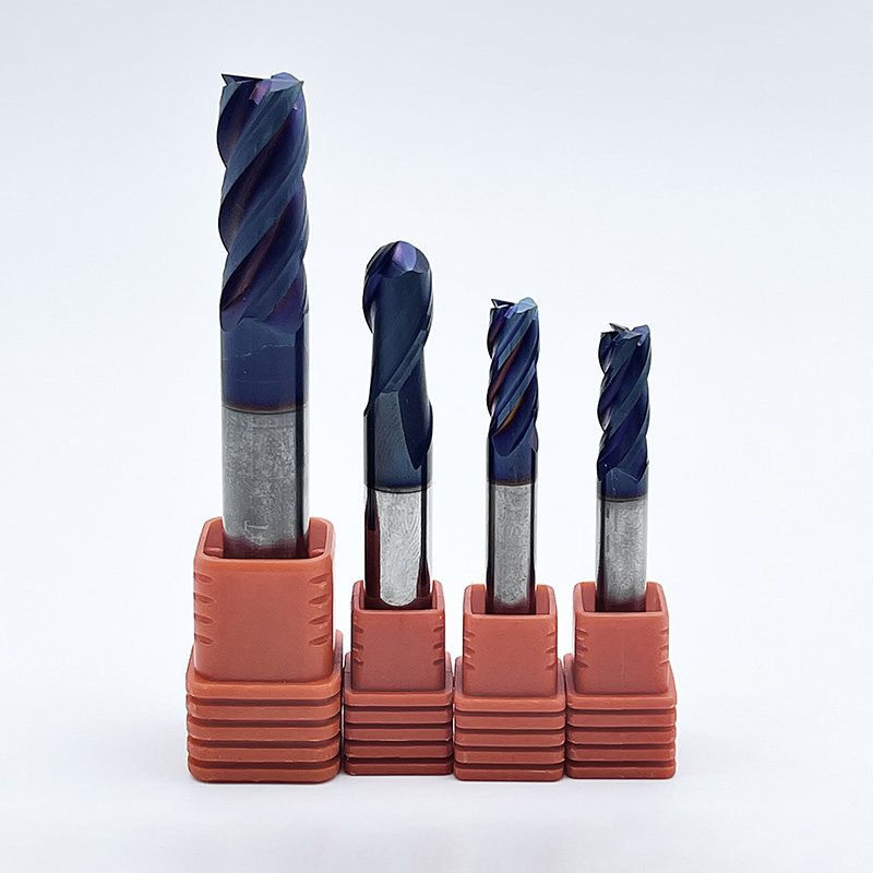
Coating and Geometry Multipliers: Selecting the right helix angle and utilizing a coated four flute cutter significantly extends tool life and alters the thermal dynamics of the cutting zone.
Tool deflection follows strict physical laws based on the cantilever beam equation. Rigidity increases by the fourth power of the core diameter. If you increase the core thickness slightly, the tool becomes exponentially stiffer. A 4 flute geometry inherently requires a thicker web compared to lower flute counts. Manufacturers leave significantly more carbide material on the tool axis to physically support the four distinct cutting edges. This structural design drastically reduces deflection under heavy radial loads.
You achieve tighter dimensional accuracy on vertical walls because the tool resists pushing away from the workpiece. When machining deep pockets with long tool stick-out, this core strength becomes the only thing preventing severe wall taper. Continuous edge engagement also creates inherently more stable cutting conditions. As one cutting edge exits the material, another has already entered. This constant contact prevents the tool from bouncing, reducing the shock loads transmitted into the machine spindle and extending the life of your spindle bearings.
The flute valley curls and evacuates the metal chip away from the cutting zone. You face a direct physical trade-off here. Thicker cores dictate shallower flutes. Shallow flutes restrict the physical volume available for chip flow. During aggressive roughing passes, the tool generates massive volumes of metal chips. If the chip volume exceeds the gullet capacity, you risk severe chip packing.
When chips compress and clog the flutes, friction spikes instantly. Temperatures soar, the carbide substrate weakens, and the tool snaps. Managing this gullet capacity determines your maximum radial depth of cut (RDOC). You must ensure the chip has enough physical space to form, curl, and eject before the tool rotates back into the cut. This is why programming the correct step-over is non-negotiable when running higher flute counts.
Machinists frame the 4 flute design as the optimal intersection for general-purpose and high-performance ferrous machining. Baseline metrics show it offers roughly 50% more core strength than a standard 2-flute tool. However, it sacrifices about 30% of its chip clearance to achieve this rigidity. Contrast this geometry with 6- or 8-flute end mills. Higher flute counts possess severely restricted gullets.
They cannot handle heavy material removal despite their massive core strength. The chips simply have nowhere to go. The 4 flute remains superior for general roughing because it clears chips effectively while resisting deflection. It hits the sweet spot for medium-to-heavy radial engagement in harder materials, allowing you to push the machine without constantly worrying about chip evacuation failures.
You should position this tool as the definitive steel milling end mill. Short, brittle chips produced by A36, 1018, and 4140 steels require significantly less flute space. These chips break easily and evacuate quickly from the cutting zone. Because chip packing poses less threat in these materials, you must prioritize the tool's core strength.
The extra rigidity handles the higher cutting forces required to shear carbon steel. You can push the tool harder, increasing your feed rates without worrying about snapping the carbide. The four cutting edges distribute the immense heat generated by cutting steel, preventing premature edge wear. When cutting 4140 pre-hardened steel, the 4 flute geometry provides the exact stability needed to maintain tool life across long production runs.
Austenitic stainless steels work-harden rapidly during the machining process. If the cutting edge rubs instead of shearing, the material surface becomes incredibly tough. A four flute carbide end mill allows you to maintain aggressive feed rates to stay ahead of this work-hardened zone. You achieve this heavy chip load without sacrificing tool rigidity.
Compare 4 flute versus 6 or 8 flute strategies for 304 and 316 stainless. The 4 flute acts as the versatile choice for mixed roughing and slotting operations. The gullets remain large enough to clear the stringier stainless chips. You should reserve 6+ flutes strictly for high-speed dynamic milling (HEM) or light finishing passes where chip volume is practically zero. If you attempt to slot stainless with a 6-flute tool, it will pack with chips and break within seconds.
End Mill Flute Count Material Suitability Matrix
Flute Count | Primary Material | Chip Clearance | Core Strength | Best Application |
|---|---|---|---|---|
2 Flute | Aluminum, Plastics | Maximum | Low | Heavy roughing and slotting in gummy materials. |
3 Flute | Aluminum, Non-Ferrous | High | Medium | High-speed profiling in aluminum. |
4 Flute | Carbon Steel, Stainless | Medium | High | General purpose roughing and finishing in ferrous metals. |
6+ Flute | Titanium, Superalloys | Minimum | Maximum | Dynamic milling (HEM) and fine finishing. |
Machinists often make the catastrophic error of using 4 flutes on non-ferrous, gummy materials. Aluminum forms long, stringy chips that do not break easily. These chips weld directly to the cutting edge inside confined 4 flute gullets. This phenomenon, known as Built-Up Edge (BUE), destroys the tool geometry and ruins the part finish.
The welded aluminum alters the cutting physics, turning a sharp edge into a blunt hammer. You can mitigate this risk only in rare edge-case exceptions. Highly rigid setups using very light radial depths of cut for finishing passes can succeed. Otherwise, you must avoid 4 flutes for aluminum and switch to a 2- or 3-flute design. Using the wrong flute count in aluminum will stall the spindle or pull the part right out of the vise.
Standard 30-degree helix angles provide strong, robust cutting edges for heavy roughing applications. They direct cutting forces axially, stabilizing the workpiece and pushing it down into the fixture. High-helix designs exceeding 45 degrees shear material more cleanly and pull chips up and out of the pocket much faster. This lifting action is excellent for chip evacuation but requires secure workholding to prevent lifting the part.
Variable helix and variable pitch designs disrupt harmonic frequencies during the cut. By spacing the cutting edges unevenly, they prevent the tool from vibrating at its natural resonant frequency. This geometry eliminates chatter and improves chip evacuation simultaneously. You can run variable pitch tools at significantly higher depths of cut without inducing vibration, making them the standard for modern high-efficiency milling.
Evaluate the four flute square end mill for sharp 90-degree corners and precise bottoming applications. It creates perfectly flat floors in pockets. However, the sharp corner is the weakest point on the tool and the first place to chip during heavy roughing.
Contrast this profile with corner radius or bullnose designs. A corner radius prevents corner chipping in hardened steels by removing the weakest point of the carbide. It also improves overall cutting force distribution. The radius thins the chip at the bottom edge, aiding in smoother chip formation and extending tool life. For heavy roughing, a corner radius always outperforms a square profile in durability. You should only use a square profile when the print explicitly calls for a sharp internal corner.
High-heat applications demand advanced thermal protection. Physical Vapor Deposition (PVD) coatings like TiAlN and AlTiN provide exceptional return on investment. A coated four flute cutter increases surface hardness and adds critical lubricity. This lubricity compensates for the friction generated by the reduced chip space of a 4 flute design.
The coating acts as a thermal barrier. It forces the heat generated by the shearing action into the chip rather than the carbide substrate. AlTiN coatings actually form a microscopic layer of aluminum oxide when exposed to high cutting temperatures, further protecting the tool. This allows you to run the tool dry with air blast, which is often superior to liquid coolant when milling steel.
Calculate your Material Removal Rate (MRR) using a standard mathematical framework. Feed rate equals RPM multiplied by the number of flutes and the recommended chip load per tooth (IPT). Moving from a 2-flute to a 4-flute mathematically doubles your feed rate potential at the exact same RPM and chip load.
For example, if you run a 1/2-inch tool at 3000 RPM with a 0.002" chip load, a 2-flute feeds at 12 inches per minute (IPM). A 4-flute feeds at 24 IPM. At a constant feed rate, a 4 flute distributes the cutting force across twice as many edges. This effectively halves the chip load per tooth and significantly extends tool life. You can push production faster while maintaining process reliability.
Core strength directly impacts wall straightness in deep profiling operations. When tool stick-out increases, the length-to-diameter (L/D) ratio grows. A high L/D ratio amplifies deflection exponentially. If you have a 3:1 L/D ratio, deflection is manageable. If you push to a 5:1 L/D ratio, deflection becomes a major problem.
The inherent rigidity of a 4 flute becomes an absolute necessity here. It resists the radial push-off forces generated during the cut. This resistance ensures the top and bottom of your milled wall measure exactly the same. You eliminate the need for multiple spring passes to correct tapered walls, saving valuable cycle time and reducing tool wear.
More cutting edges typically yield a superior surface finish. The tool creates a smaller scallop height per revolution across the material. Increased core stability prevents micro-vibrations from transferring to the workpiece surface. When you measure the surface roughness (Ra), a stable 4-flute tool consistently outperforms a 2-flute tool in steel.
Transitioning from roughing to finishing requires a strategy shift. Roughing prioritizes maximum chip clearance and material removal. Finishing dictates that rigidity and edge count control the surface finish. A 4 flute provides the perfect stability required to achieve mirror-like finishes on steel components, provided your runout is kept to an absolute minimum.
Chatter leaves distinct visual chatter marks on your part and sounds like a high-pitched squeal. Excessive tool engagement, poor fixturing, or a lack of machine rigidity usually causes this destructive vibration. You can mitigate chatter by immediately reducing your axial depth of cut (ADOC) or adjusting your spindle speed to find a stable machining zone.
Alternatively, switch to a variable pitch geometry to break the harmonic resonance. Ensure your tool holder provides maximum runout accuracy. Shrink fit or hydraulic holders are vastly superior to standard ER collets for this. Even a few tenths of runout will cause one flute to take a heavier chip load, inducing severe vibration and premature tool failure.
Confined spaces expose the primary weakness of the 4 flute end mill. Chips struggle to escape deep pockets due to the smaller gullet volume. The tool recuts these hardened chips, instantly destroying the cutting edges. You must utilize specific toolpath strategies to manage this risk.
Trochoidal milling and High-Efficiency Milling (HEM) utilize a very low radial depth of cut (RDOC) combined with a high axial depth. This strategy manages chip volume, keeps the tool cool, and prevents catastrophic clogging in deep cavities. By taking a thin chip, the heat transfers into the chip rather than the tool, allowing the chips to evacuate easily without packing the flutes.
Coolant application depends entirely on the workpiece material and the specific tool coating. Use high-pressure flood coolant for austenitic stainless steel to provide necessary lubricity and prevent work hardening. The coolant flushes the sticky chips out of the cutting zone.
Switch to high-pressure air blast for steel milling with coated carbide. Air blast evacuates chips effectively without causing thermal shock. Pumping liquid coolant onto a super-heated coated tool causes rapid expansion and contraction. This thermal shock creates micro-fractures in the carbide substrate, leading to premature edge failure. Let the coating do its job and use air to clear the chips.
The 4 flute end mill stands as the essential workhorse for ferrous machining. It perfectly balances the need for structural rigidity against adequate chip evacuation. When planning your machining operations, apply a simple shortlisting logic. Choose 4 flutes for general steel and stainless applications. Step down to 2 or 3 flutes for aluminum and heavy slotting. Step up to 5 or more flutes for dedicated high-speed finishing or dynamic milling in titanium and superalloys.
Audit your current tool crib to remove standard helix tools and replace them with variable pitch geometries for roughing.
Adjust your CAM software to utilize HEM toolpaths, maximizing the MRR of your rigid tools while protecting the gullets from chip packing.
Standardize your shop floor procedures to use air blast instead of flood coolant when roughing steel with coated carbide.
Measure your tool holder runout with a dial indicator to ensure even chip load distribution across all four flutes before running the program.
A: Machinists use them primarily for cutting ferrous metals, carbon steels, and tool steels. They provide the ideal balance between core strength for roughing and edge count for finishing operations. This makes them the standard choice for general-purpose metalworking.
A: Generally, you should avoid it. Aluminum produces stringy chips that easily clog the smaller gullets of a 4 flute tool. This leads to chip welding and tool breakage. However, you can use them for very light finishing passes where chip volume is minimal.
A: Higher flute counts produce better surface finishes. More cutting edges engaged per revolution reduce the scallop height left on the material. The thicker core also minimizes vibration, resulting in a smoother, cleaner cut.
A: Manufacturers must leave more carbide material in the center to support the four distinct cutting edges. This geometry inherently reduces the depth of the flute valleys but exponentially increases the tool's resistance to deflection.
A: Standard helix tools have evenly spaced cutting edges. Variable helix tools stagger the angles and spacing of the flutes. This staggered design breaks up harmonic frequencies, eliminating chatter and allowing for heavier cuts.
A: Yes. A corner radius removes the sharp, fragile tip of the square profile. This prevents corner chipping during heavy roughing in hardened steels and distributes cutting forces more evenly across the bottom edge.