English
- All
- Product Name
- Product Keyword
- Product Model
- Product Summary
- Product Description
- Multi Field Search

Views: 0 Author: Site Editor Publish Time: 2026-08-24 Origin: Site

In precision CNC machining, tooling selection directly dictates cycle times, surface finish quality, and overall profitability. Utilizing the wrong cutter leads to catastrophic tool failure, scrapped workpieces, and eroded margins. Machinists and shop managers face an overwhelming matrix of tool geometries, coatings, and substrates. Balancing high-performance requirements with cost-per-part realities makes standardizing tool cribs a complex engineering challenge. You cannot simply guess which tool will perform best under heavy cutting loads. The physics of metal removal demand precise matching of cutter geometry to workpiece material. This guide provides a systematic, engineering-first framework for evaluating and selecting metric carbide end mills. We bridge the gap between theoretical tool specifications and practical machining realities. You will learn how to analyze spindle capabilities, match flute counts to material types, and optimize toolpaths for maximum efficiency.
Solid carbide possesses distinct metallurgical advantages over traditional High-Speed Steel. Carbide is a composite material manufactured through powder metallurgy. It combines tungsten carbide particles with a cobalt binder. This structure delivers superior hardness and exceptional wear resistance. Carbide maintains its sharp cutting edges at highly elevated temperatures. This thermal stability allows for aggressive surface footage (SFM) during machining. You can push carbide tools much faster than HSS equivalents. High-speed machining generates intense heat at the shear zone. Carbide absorbs and dissipates this heat effectively without losing structural integrity. This makes it ideal for cutting tough alloys and hardened steels.
When cutting 4140 pre-hardened steel, a carbide cutter can easily run at 400 SFM. An HSS tool would burn up instantly at those speeds, requiring a drop to 80 SFM or lower. This speed differential directly translates to faster cycle times. The rigidity of the tungsten carbide matrix also prevents the tool from flexing under heavy radial loads. Less flex means tighter tolerances on the finished part. Furthermore, carbide tools excel in dry machining applications where air blasts clear chips. The heat transfers into the chip rather than the tool, preserving the cutting edge.
High-Speed Steel offers different mechanical properties. HSS features higher toughness and transverse rupture strength. It is significantly more forgiving in less rigid machining setups. If your spindle has excessive runout, HSS will bend slightly rather than shatter. However, HSS has strict speed limitations. It softens rapidly under high thermal loads. This susceptibility leads to faster wear rates in abrasive materials. HSS tools also experience more chatter during heavy cuts. They simply lack the stiffness required for modern, high-efficiency milling strategies. While HSS has its place in manual machining, CNC environments demand the rigidity of carbide.
Tooling budgets require careful analysis of cost-to-performance ratios. The industry-standard threshold revolves around the 8mm diameter mark. Solid carbide is universally recommended for metric end mills under 8mm. At these smaller diameters, the raw material cost is relatively low. The price difference between HSS and carbide is negligible. However, the performance gains are massive. Small carbide tools operate at high RPMs without deflecting. They deliver superior surface finishes and extended tool life. Standardizing on carbide for all small-diameter work is a sound engineering practice.
Consider a 4mm cutter profiling a 6061-T6 aluminum bracket. A carbide tool can run at 12,000 RPM and feed at 2,500 mm/min. An HSS tool would struggle to hit half those metrics without excessive wear. The time saved on a single production run pays for the carbide tool multiple times over. The calculation changes for larger diameters. Above 12mm, the cost of solid carbide scales exponentially. A 20mm solid carbide end mill represents a significant financial investment. For these larger sizes, you must evaluate the specific production run. High-volume production justifies the cost through faster cycle times. Budget-constrained or low-volume runs require alternative strategies. Indexable tooling often replaces solid carbide at larger diameters. Indexable cutters use small carbide inserts on a steel body. This provides carbide performance at a fraction of the solid tool cost. HSS remains a viable option for large, low-speed roughing in soft materials.
Roughing operations prioritize maximum material removal rates (MRR). You must manage high chip volumes and heavy cutting depths. Tool geometry must facilitate rapid chip evacuation. Specialized roughing end mills feature corn-cob or chipbreaker geometries. These designs break long chips into smaller, manageable pieces. This prevents chips from packing in the flutes and breaking the tool. Lower flute counts also benefit roughing operations. Fewer flutes create larger chip gullets. Large gullets allow massive amounts of material to escape the cutting zone. Roughing tools focus on strength and clearance over surface finish.
When programming a roughing pass, you might engage 40% of the tool's diameter radially and 150% axially. This generates a massive volume of chips. If those chips stay in the cutting zone, they get recut. Recutting chips destroys the cutting edge and spikes the spindle load. Chipbreakers solve this by shearing the material into fine dust or small chips. Finishing operations shift the focus entirely. The primary goal is achieving precise surface-finish targets. Finishing requires higher flute counts and specific helix angles. More flutes mean more cutting edges engage the material per revolution. This allows for higher feed rates while maintaining a low chip load per tooth. Finishing toolpaths utilize lighter radial depths of cut. The tool barely skims the surface of the workpiece. High flute counts reduce tool deflection during these light cuts. Specialized helix angles help shear the material cleanly. This combination produces superior wall finishes and tight dimensional accuracy.
Selecting the correct flute count is critical for process stability. For non-ferrous materials like aluminum and plastics, utilize 2 to 3 flutes. These materials produce large, stringy chips. Large chip gullets are mandatory to prevent material packing. If chips cannot escape, they weld to the cutting edge. This phenomenon is known as built-up edge (BUE). BUE destroys surface finish and rapidly snaps the tool. A 3-flute design offers the perfect balance. It provides ample chip clearance while maintaining enough core strength for aggressive feed rates.
Ferrous materials require a different approach. Steels, cast iron, and titanium produce smaller, tighter chips. Chip volume is lower, so massive gullets are unnecessary. Specify 4 to 6 or more flutes for these materials. Higher flute counts maximize feed rates and improve surface finish. More importantly, they increase the core diameter of the tool. A larger core drastically improves tool strength and rigidity. This rigidity is essential when cutting tough alloys. It minimizes deflection and prevents chatter during heavy engagement.
When machining 304 stainless steel, a 5-flute cutter outperforms a 4-flute cutter. The extra flute increases the core diameter by roughly 15%. That added mass dampens vibration. It also allows you to increase the feed rate by 25% while maintaining the exact same chip load per tooth. For titanium alloys like Ti-6Al-4V, 6-flute or even 7-flute designs are becoming standard. These high-flute-count tools allow for dynamic milling strategies where the radial engagement is kept extremely low, but the axial depth of cut spans the entire flute length.
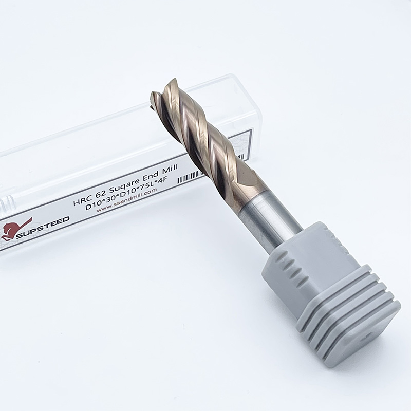
The profile of the cutting end determines the tool's application. Evaluate square end mills for standard slotting and profiling. They are essential when sharp 90-degree corners are required at the bottom of a pocket. Square profiles excel at plunging and peripheral milling. However, the sharp corners are highly susceptible to chipping. The stress of the cut concentrates directly on the fragile tip. You must carefully manage feed rates when plunging with square tools.
Ball nose end mills serve a completely different function. Evaluate them for 3D contouring and complex surfacing. The fully radiused end allows for smooth transitions across curved surfaces. Ball nose tools are heavily utilized in mold making and multi-axis finishing operations. They leave a scalloped finish that requires careful stepover calculations. The center of a ball nose tool has a cutting speed of zero. You must tilt the tool or use a lead angle to engage the effective cutting diameter.
Corner radius, or bull nose, profiles offer the best of both worlds. Highlight this as the optimal choice for roughing operations. The radius mitigates stress concentrations at the tool tip. This drastically reduces chipping in the brittle solid carbide. A corner radius tool can handle much heavier chip loads than a square tool. It distributes the cutting forces over a larger area. Always specify a corner radius unless a sharp internal corner is strictly required by the blueprint.
Tool dimensions dictate the mechanical stability of the machining process. The fundamental engineering rule of thumb is critical. Tool deflection increases to the third power of the overhanging length. If you double the length of the tool sticking out of the holder, deflection increases eightfold. Deflection causes chatter, poor surface finish, and rapid tool failure. You must manage tool length ruthlessly.
Always select the largest possible diameter that fits the part geometry. A larger diameter exponentially increases the tool's stiffness. Match the Length of Cut (LOC) strictly to the maximum cutting depth dictated by the feature. Do not use a tool with a 25mm LOC to cut a 10mm deep pocket. The extra length serves no purpose and compromises rigidity. Similarly, minimize the Overall Length (OAL). Keep the tool choked up as close to the collet as possible. Short, stubby tools perform infinitely better than long, slender ones.
Machinists refer to the Length-to-Diameter (L/D) ratio. An L/D ratio of 3:1 is highly stable. An L/D ratio of 5:1 requires reduced feed rates and careful toolpath generation. Anything over 8:1 is considered deep cavity milling and requires specialized vibration-dampening tool holders and extremely light radial engagement.
Standard Tool Dimensions and Applications
| Diameter (mm) | Primary Application Focus | Recommended Flute Count (Ferrous) | Recommended Flute Count (Non-Ferrous) |
|---|---|---|---|
| 3mm | Micro-machining, fine detailing, tight internal radii | 4 Flutes | 2 Flutes |
| 4mm | Small pocketing, intricate profiling, mold finishing | 4 Flutes | 2 to 3 Flutes |
| 6mm | General purpose slotting, light roughing operations | 4 to 5 Flutes | 3 Flutes |
| 8mm | High-efficiency milling, standard production profiling | 4 to 6 Flutes | 3 Flutes |
| 10mm | Heavy roughing, deep pocketing, rigid setups | 5 to 6 Flutes | 3 Flutes |
| 12mm | Aggressive material removal, structural aerospace parts | 6+ Flutes | 3 Flutes |
| 16mm | High-torque roughing, large scale face milling | 6+ Flutes | 3 Flutes |
| 20mm | Massive material removal, heavy industrial components | 6 to 8 Flutes | 3 Flutes |
Global manufacturing relies on standardized tooling dimensions. Common metric end mill sizes follow specific increments. The most frequently utilized diameters include 3mm, 4mm, 6mm, 8mm, 10mm, 12mm, 16mm, and 20mm. Designing parts around these standard sizes reduces tooling costs. Custom diameters require expensive grinding and long lead times. By standardizing your tool crib around these core metric dimensions, you streamline inventory management. You also ensure immediate availability from major tooling suppliers.
Precision tool holding is just as important as the tool itself. High-performance carbide requires tight shank tolerances. Most premium metric cutters feature an h6 precision shank tolerance. This tight tolerance is mandatory for advanced tool holding systems. Shrink-fit holders and hydraulic chucks rely on exact shank dimensions to function. These advanced holders provide massive gripping force and exceptional concentricity. Standard ER collets often lack the precision required for high-speed carbide milling. Upgrading your tool holders maximizes the return on your carbide tooling investment.
Tool coatings alter the tribological properties of the cutting edge. They reduce friction, resist heat, and extend tool life. However, applying the wrong coating causes immediate failure. For aluminum and non-ferrous applications, evaluate Uncoated, ZrN, or TiB2 options. Aluminum is highly reactive and gummy. It tends to weld to standard coatings. Uncoated tools feature polished flutes that maintain high lubricity. ZrN (Zirconium Nitride) and TiB2 (Titanium Diboride) coatings provide a hard, slick surface that completely prevents built-up edge (BUE). Never use aluminum-based coatings when cutting aluminum, as the chemical affinity will cause the workpiece material to fuse directly to the cutter.
High-temperature alloys and steels require different protection. Evaluate TiAlN and AlTiN coatings for these demanding materials. These advanced coatings possess a unique chemical property. Under extreme cutting heat, they form a protective aluminum oxide layer on the tool surface. This microscopic ceramic layer acts as a thermal barrier. It reflects heat back into the chip and away from the carbide substrate. This makes AlTiN coatings ideal for dry machining applications. Using coolant with these coatings can actually cause thermal shock and micro-fracturing.
Common Carbide Tool Coatings and Material Compatibility
| Coating Type | Primary Material Application | Key Benefit | Coolant Recommendation |
|---|---|---|---|
| Uncoated (Polished) | Aluminum, Plastics, Brass | Maximum lubricity, prevents chip welding | Flood coolant or air blast |
| ZrN (Zirconium Nitride) | Abrasive Non-Ferrous, Copper | High hardness, excellent BUE resistance | Flood coolant |
| TiAlN (Titanium Aluminum Nitride) | Cast Iron, Carbon Steels, 400 Series SS | High thermal stability, oxidation resistance | Dry or air blast preferred |
| AlTiN (Aluminum Titanium Nitride) | Inconel, Titanium, Hardened Steels | Extreme heat resistance, forms ceramic layer | Strictly dry or air blast |
Chatter is the enemy of solid carbide. It destroys surface finish and shatters cutting edges. Standard end mills feature equal spacing between flutes and a constant helix angle. As these tools cut, they generate rhythmic impacts. These impacts create resonant frequencies that build into violent chatter. Variable helix and variable pitch designs solve this problem through harmonic dampening. By altering the spacing and angle of each flute, the tool breaks up resonant frequencies. The rhythmic impacts are disrupted, preventing chatter from amplifying.
This variable geometry is a mandatory requirement for modern machining strategies. High-Efficiency Milling (HEM) and aggressive trochoidal toolpaths rely on high feed rates and deep axial engagement. These toolpaths generate immense radial forces. A standard end mill will scream and chatter under these conditions. Variable pitch tools absorb these forces smoothly. They allow you to utilize the entire length of cut without vibration. If you are programming HEM toolpaths, variable geometry carbide is non-negotiable.
Deploying premium tooling involves significant implementation risks. The primary risk stems from the material properties of the cutter. Solid carbide is incredibly hard, but it is highly brittle. It does not tolerate vibration, runout, or sudden impacts. Running carbide in loose, worn, or low-RPM spindles leads to immediate micro-chipping. This micro-chipping rapidly progresses to catastrophic shattering. Your machine tool must provide a rigid, stable platform. If the spindle bearings are failing, carbide tools will not survive.
You must also understand the inverse relationship between tool diameter and spindle speed. Larger cutters require significantly lower RPMs to maintain the correct surface footage. However, cutting at lower RPMs demands much higher spindle torque. A 20mm carbide cutter taking a heavy roughing pass requires massive torque. This torque requirement may easily exceed the capabilities of entry-level or lightweight CNC machines equipped with BT30 or ISO30 spindles. These smaller spindles excel at high RPMs but lack the low-end grunt needed to push large carbide tools through steel. Stalling the spindle during a cut will destroy the tool and potentially damage the machine. Conversely, a heavy-duty CAT50 or HSK-A100 machine provides the necessary rigidity and torque to maximize the material removal rate of large metric cutters.
Implement strict mitigation strategies before deploying expensive carbide. Verify spindle runout using a precision dial indicator. Check the machine axes for backlash and lost motion. Ensure the workholding setup is absolutely rigid. Flimsy vises or inadequate clamping will induce vibration regardless of tool quality. Match the tool diameter to the continuous torque curve of your specific spindle motor. Proper preparation prevents costly tooling failures.
Runout is the silent killer of solid carbide tools. Runout occurs when the tool rotates off-center from the spindle axis. Even microscopic amounts of runout cause severe problems. Consider a 4-flute cutter with just 0.01mm of runout. That tiny deviation disproportionately loads one single flute. One cutting edge takes a massive chip, while the others barely touch the material. This uneven loading cuts the theoretical tool life of the cutter in half. It also causes dimensional inaccuracies in the workpiece.
Standard tool holding methods often introduce unacceptable runout. ER collet systems are versatile but prone to debris contamination and wear. A single chip caught inside the collet taper will throw the tool off-center. When evaluating high-end carbide investments, advise your team to upgrade the tool holding. Transition from standard ER collets to precision milling chucks, hydraulic holders, or shrink-fit systems. Shrink-fit holders use thermal expansion to grip the tool shank uniformly across its entire circumference. These advanced holders guarantee runout below 0.003mm. Eliminating runout ensures all flutes share the cutting load equally. This maximizes tool life and justifies the initial tooling expense.
Follow this systematic process to verify tool runout before machining:
A: Solid carbide offers superior hardness, extreme heat resistance, and supports much higher cutting speeds (SFM). It is ideal for high-production CNC environments. HSS (High-Speed Steel) is tougher and less brittle, making it more forgiving in less rigid setups or manual machines. However, HSS wears faster and operates at significantly lower speeds.
A: Roughing operations require tools designed for high chip volume and heavy cutting depths. These tools often utilize chipbreakers or lower flute counts to maximize material removal. Finishing operations require higher flute counts and specific helix angles to achieve optimal surface finishes and tight dimensional tolerances.
A: The general rule of thumb depends on the material. Use 2 to 3 flutes for aluminum and non-ferrous materials to provide large gullets for chip clearance. Use 4 or more flutes for steel, cast iron, and ferrous materials to increase core strength and improve surface finish.
A: The global manufacturing industry standardizes around specific metric increments. The most common sizes include 3mm, 4mm, 6mm, 8mm, 10mm, 12mm, 16mm, and 20mm. Designing parts and standardizing tool cribs around these sizes ensures availability and reduces custom tooling costs.
A: Solid carbide is highly brittle. Even 0.01mm of runout forces one flute to take a disproportionately large chip load. This uneven cutting force causes micro-chipping, poor surface finish, and can cut the tool's expected lifespan in half. Precision tool holding is mandatory.
A: Always use a corner radius (bull nose) profile for roughing operations unless a sharp 90-degree internal corner is required. The radius mitigates stress concentrations at the fragile tip of the tool. This prevents chipping, increases strength, and extends the life of the cutter under heavy loads.