- All
- Product Name
- Product Keyword
- Product Model
- Product Summary
- Product Description
- Multi Field Search

Views: 0 Author: Site Editor Publish Time: 2026-08-10 Origin: Site

Factory-induced tool runout carries a compounding cost for any machining operation. Even a few tenths of a thousandth of an inch (0.0001") of runout can reduce tool life by up to 50%. This rapid degradation occurs due to uneven chip load, accelerated flute wear, and unbalanced cutting forces. Machinists frequently spend hours cleaning spindles and meticulously dialing in premium tool holders to minimize runout on the shop floor. However, if the end mill itself lacks shank-to-flute concentricity straight from the factory, you face a losing battle. In-machine adjustments cannot correct this inherent geometric flaw.
To prevent catastrophic tool failure, avoid part scrappage, and ensure predictable surface finishes, procurement and tooling managers must take proactive steps. You must understand the specific metrology and Quality Assurance (QA) protocols a reputable end mill manufacturer uses before a tool is boxed and shipped. Knowing how your supplier inspects concentricity empowers you to make better tooling decisions.
Concentricity Starts at the Blank: True runout prevention begins during the centerless grinding of the carbide blank, long before flutes are milled.
Optical vs. Contact Metrology: Leading manufacturers utilize automated optical measurement systems (e.g., Zoller, Walter Helicheck) to inspect dynamic runout without damaging the cutting edge.
Coating Complications: A reliable coated end mill manufacturer must perform secondary runout inspections post-coating, as uneven PVD/CVD deposition can introduce microscopic concentricity errors.
TIR Tolerance Stacking: Machinists must understand Total Indicated Runout (TIR) stack-up; factory tool runout directly compounds with holder and spindle runout.
Supplier Evaluation: Buyers should demand batch inspection reports and verify whether a supplier uses 100% inspection or statistical sampling for high-performance tooling lines.
Uneven flute engagement destroys cutting tools. Factory-induced runout forces one or two flutes to take a heavier chip load than the rest. This imbalance leads to localized heat buildup along the cutting edge. Micro-chipping soon follows, resulting in premature tool failure. When flutes do not share the cutting load equally, the tool cannot perform at its intended feed rate. You end up backing off parameters just to keep the tool intact, which kills cycle times and throughput.
Total Indicated Runout (TIR) stack-up is a core concept for machinists. Tolerance stacking means that errors multiply across the assembly. A minuscule factory runout of 0.0001" on the end mill shank compounds exponentially. When you pair this flaw with minor collet, tool holder, and spindle runout, the total error becomes unmanageable. The entire machining system loses rigidity. A tool holder might have 0.0002" of runout, and the spindle might add another 0.0001". If the tool itself brings 0.0003" to the table, you are suddenly looking at over half a thousandth of total runout at the cutting tip.
Uneven flute engagement shifts the center of cutting forces during rotation. This shift causes cyclical deflection and chatter. Rapid machine spindle wear is a direct consequence of these cyclical cutting force spikes. Bearings degrade faster when subjected to constant, unbalanced radial loads. Over months of production, this translates to premature spindle rebuilds and lost machine availability.
Surface finish degradation directly correlates with tool runout. Chatter and vibration leave visible marks on the workpiece. Poor surface finish values (Ra/Rz) often force secondary polishing operations. This is particularly problematic in critical finishing passes where dimensional accuracy is paramount. If you are milling a mold cavity, a poor finish means hours of manual bench work.
Partnering with a rigorous solid carbide end mill manufacturer is a baseline requirement for process stability. Consistent tool geometry ensures predictable machining outcomes across multiple production runs. You need to know that tool number fifty will cut exactly like tool number one.
| Runout Level (Inches) | Impact on Tool Life | Surface Finish Effect | Spindle Wear Risk |
|---|---|---|---|
| 0.0001" - 0.0002" | Normal expected life | Excellent (Ra < 16) | Minimal |
| 0.0003" - 0.0005" | 20% to 30% reduction | Visible chatter marks | Moderate bearing stress |
| 0.0006" - 0.0010" | 50% reduction or immediate failure | Unacceptable (Ra > 63) | High risk of premature failure |
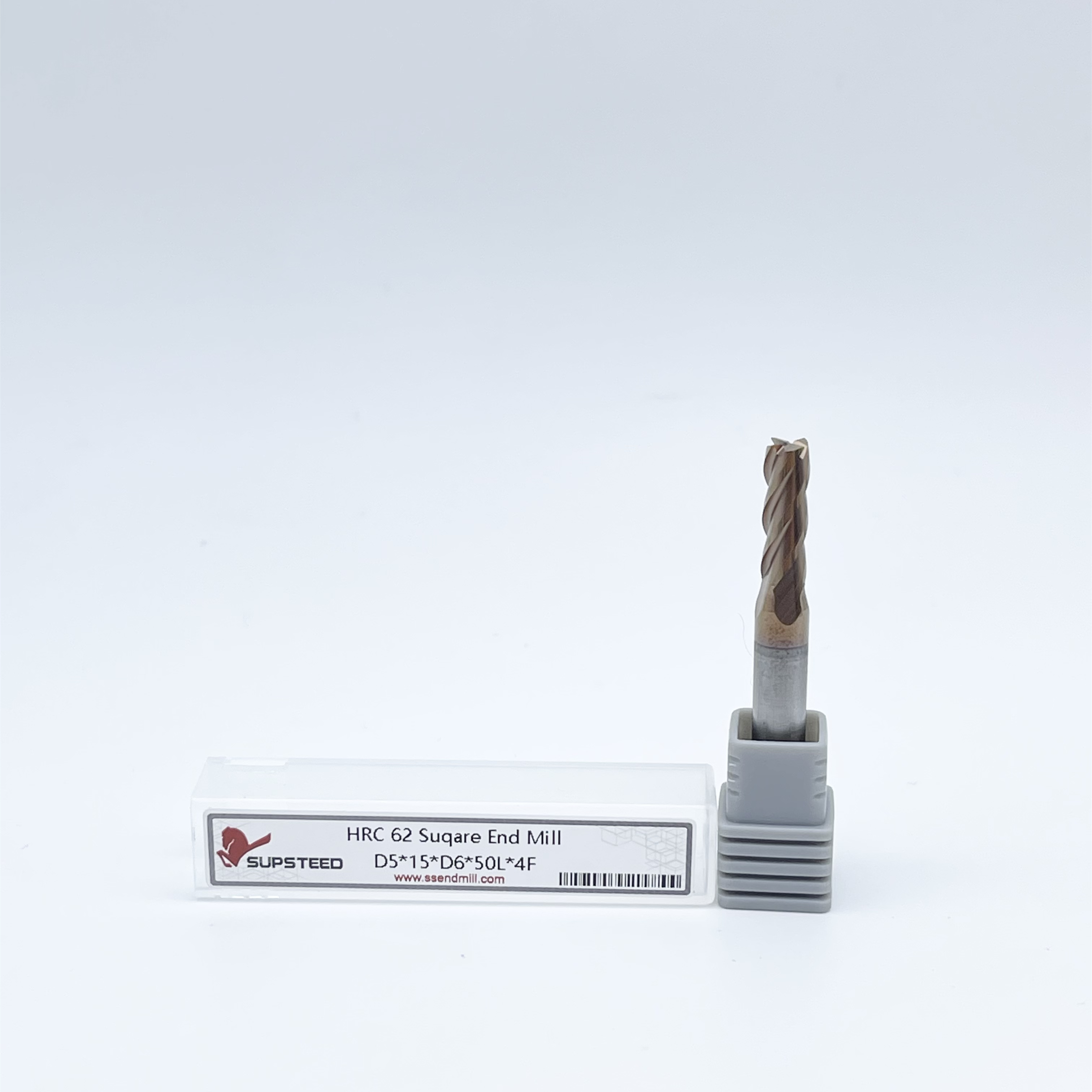
Isolating tool-only runout requires strict environmental controls. A premium manufacturer must separate the tool's geometry from the inspection fixture. They use ultra-precision master spindles with inherent runout under 0.00002". Strict cleaning protocols ensure that dust or oil does not skew measurement data. Fixture errors must be eliminated to get an accurate reading of the tool itself. If the inspection environment is flawed, the data is useless.
Leading facilities rely on non-contact optical comparators and laser metrology. These systems measure the cutting diameter, core diameter, and runout across the entire flute length simultaneously. They do this without touching delicate cutting edges. Physical contact can chip sub-micron edge preparations. Optical systems provide high-resolution, repeatable data for complex helical geometries. Machines from brands like Zoller or Walter Helicheck use high-megapixel cameras and custom lighting arrays to capture the exact profile of the tool as it rotates.
Traditional QA methods still have a place in the factory. Rolling a shank on precision V-blocks with a sub-micron dial indicator checks baseline shank concentricity. However, this method is insufficient for complex helical flute geometries. Contact metrology cannot accurately map the entire cutting edge profile. It remains a quick, effective check for the unground shank portion of the blank before it enters the CNC grinder.
Measuring a stationary tool provides static runout data. Measuring dynamic runout involves rotating the tool at inspection speeds. Dynamic inspection simulates real-world spindle conditions. It reveals how the tool behaves under rotational forces. High-performance tooling requires dynamic inspection to guarantee stability at high RPMs. A tool might look perfectly straight sitting on a bench, but once it spins at 15,000 RPM, mass imbalances can induce dynamic runout.
Different materials demand different runout tolerances. The application dictates the acceptable margin of error. Machining exotic alloys requires near-perfect concentricity to prevent work hardening and tool breakage. You cannot apply general-purpose aluminum cutting standards to aerospace superalloys.
Aerospace applications demand stringent QA requirements from a titanium end mill manufacturer. Titanium has low thermal conductivity. It tends to work-harden rapidly. This material is highly intolerant to rubbing. Runout causes rubbing, which induces massive heat. Heat destroys the cutting edge and ruins the titanium workpiece. When cutting Ti-6Al-4V, even a 0.0003" runout will cause the trailing flutes to rub rather than shear, instantly spiking the temperature and destroying the tool coating.
Rigidity and concentricity are non-negotiable expectations from a hardened steel end mill supplier. Runout in high-hardness applications instantly shatters carbide flutes. The extreme, unbalanced radial cutting forces exceed the carbide's transverse rupture strength. Perfect concentricity distributes these heavy forces evenly across all flutes. When milling D2 or H13 tool steel hardened to 60 HRC, the cutting edge is under immense pressure. Any deviation in chip load will snap the flute.
Acceptable runout scales with tool diameter. A 0.0002" runout on a 1/2" end mill is manageable. However, on a 0.015" micro end mill, that same 0.0002" represents a massive percentage of the tool's diameter. In micro-machining, this level of runout is catastrophic. It guarantees immediate tool breakage. Micro-tools require specialized grinding wheels and ultra-precise workholding during manufacturing to maintain tolerances in the millionths of an inch.
| Application Type | Material Focus | Critical Runout Tolerance | Primary Failure Mode if Exceeded |
|---|---|---|---|
| Aerospace Machining | Titanium, Inconel | < 0.0001" | Work hardening, rapid edge wear due to heat |
| Hard Milling | Hardened Steel (HRC 50+) | < 0.0001" | Catastrophic flute chipping, shattered carbide |
| Micro-Machining | Various Metals | < 0.00005" | Immediate tool snapping upon engagement |
| General Purpose | Aluminum, Mild Steel | < 0.0003" | Poor surface finish, chatter marks |
Quality control is not a single event at the end of the line. It is a continuous process integrated into every stage of production. Catching eccentricities early prevents wasted grinding time on flawed blanks. A robust factory floor implements multiple gates to catch runout before the tool moves to the next operation.
Blank Preparation: The raw carbide rod is cut to length and chamfered.
Centerless Grinding: The rod is ground to the exact outer diameter required for the shank.
Fluting: CNC grinders cut the helical flutes into the solid carbide.
Edge Preparation: The cutting edges are honed or brushed to prevent micro-chipping.
Coating: The tool receives a PVD or CVD coating for heat and wear resistance.
If the raw carbide blank is not perfectly cylindrical, the final tool will inherently have runout. Centerless grinding establishes the foundational geometry. Manufacturers use laser-micrometer checks at this stage. They verify that the blank meets strict diameter and roundness tolerances before it ever sees a fluting wheel. If the blank has a taper or an oval shape, the collet in the CNC grinder will hold it off-center, guaranteeing a bad tool.
Inspection immediately follows the CNC tool and cutter grinder. This step checks the concentricity of the cutting edges relative to the shank axis. Operators use optical machines to verify the core diameter, rake angles, and relief angles. Any deviation here means the machine needs recalibration. Thermal expansion of the grinding machine during a long shift can cause the grinding wheel to drift, introducing runout into the batch.
A reliable coated end mill manufacturer plays a critical role here. They must verify that edge preparation and coating processes have not skewed the tool's concentricity. Physical vapor deposition (PVD) adds microns of material. Uneven deposition creates high spots. Post-coating inspection ensures the final product remains perfectly concentric. If the tools are packed too tightly in the coating chamber, the plasma flow can be obstructed, leading to uneven coating thickness.
Tooling buyers must navigate a market filled with varying quality levels. Identifying subpar quality control prevents costly shop floor disruptions. You must know what red flags to look for when evaluating new suppliers. Do not rely solely on marketing brochures; demand hard data.
Avoid suppliers who do not publish their runout tolerances. Transparency is key. If a manufacturer refuses to provide sample inspection reports upon request, look elsewhere. Reputable suppliers proudly display their metrology capabilities and guarantee their geometric tolerances. They will gladly show you a Zoller report for a specific batch of tools.
Low-tier suppliers often deflect blame when tools fail. They blame the machinist's collet, tool holder, or spindle for runout issues. This tactic masks their own manufacturing defects. While spindle runout is real, a properly measured tool isolates the root cause. If you measure the tool in a known-good shrink fit holder and still see excessive runout, the tool is the problem.
Microscopic grease, oil, or dust generates false runout readings. During incoming quality control (IQC), the tool shank and collet face must be spotless. A single speck of dust throws off a sub-micron dial indicator. Establish strict cleaning protocols before verifying supplier claims. Wipe down the shank with isopropyl alcohol and use a lint-free cloth before inserting it into the inspection block.
You cannot correct a bad tool. Attempting to dial in or compensate for a tool with an inherently eccentric flute-to-shank axis is highly inefficient. Adjustable holders cannot correct the structural geometry of the flutes. The tool will still cut unevenly, regardless of how you position the shank in the spindle. You might get the tip to run true, but the core of the tool will be wobbling, leading to erratic cutting forces.
Choosing a tooling partner involves balancing quality assurance with budget constraints. Higher precision requires more rigorous inspection, which impacts the final unit cost. Understanding these trade-offs helps you align procurement with production needs. You do not always need a zero-runout tool for roughing aluminum, but you absolutely need it for finishing aerospace components.
High-performance, high-tolerance lines often undergo 100% optical inspection. Every single tool is measured. General-purpose end mills may only be batch-sampled using AQL statistical sampling. 100% inspection guarantees consistency but takes more time. Analyze the cost-to-benefit ratio based on your application's tolerance requirements. If a broken tool will scrap a $10,000 titanium forging, pay for the 100% inspected end mill.
Highly regulated industries require strict traceability. Medical, aerospace, and defense sectors benefit from laser-etched serial numbers. Downloadable inspection certificates prove that the tool met specifications before use. This documentation is vital for compliance and process auditing. If a part fails in the field, you need to trace the exact cutting tool used to machine it.
Sub-micron tolerance guarantees increase the unit price of the end mill. Advanced optical metrology and slower grinding feed rates add to manufacturing expenses. However, these premium tools drastically reduce the cost-per-part. They extend tool life, eliminate unplanned downtime, and reduce scrap rates. Spending an extra $20 on a high-quality end mill can save hundreds of dollars in machine time and scrapped material.
While machinists control tool holder and spindle maintenance, the baseline concentricity of the system is permanently dictated by the end mill manufacturer's QA processes. You cannot machine accurate parts with eccentric tools. Quality control at the factory level is the foundation of shop floor stability.
Procurement teams must shortlist suppliers based on transparency. Evaluate their grinding equipment, metrology investments, and published tolerance standards. A supplier willing to share their inspection methodology is a supplier you can trust with your critical operations.
Request a batch of test end mills along with their specific optical inspection reports.
Run a controlled tool-life comparison against your current suppliers using identical machining parameters.
Implement a strict incoming quality control (IQC) cleaning protocol to verify tool runout accurately in-house.
Audit potential suppliers on their post-coating inspection processes to ensure PVD layers do not introduce runout.
A: For high-performance solid carbide end mills, acceptable factory runout is typically under 0.0002 inches (5 microns). Micro-tools and aerospace-grade end mills often require tolerances tighter than 0.0001 inches to prevent premature failure and ensure stable cutting dynamics.
A: Physical Vapor Deposition (PVD) adds a thin layer of material to the tool. If the deposition process is uneven, it creates microscopic high spots on the cutting edges or the shank. This uneven layer alters the tool's geometry, introducing dynamic runout during rotation.
A: No. While a machinist can use adjustable holders to correct runout caused by the spindle or collet, they cannot fix a tool that has an eccentric flute-to-shank axis. The inherent geometric flaw remains, causing uneven chip loads.
A: Titanium work-hardens easily and has low thermal conductivity, making it sensitive to the rubbing caused by runout. Hardened steel generates extreme radial cutting forces. Runout in these materials causes rapid heat buildup and immediate catastrophic carbide chipping.
A: Shank runout measures the concentricity of the unground cylindrical base of the tool. Cutting-edge runout measures the concentricity of the actual flutes relative to the shank axis. A tool can have a perfectly round shank but still suffer from cutting-edge runout if ground improperly.


