English
- All
- Product Name
- Product Keyword
- Product Model
- Product Summary
- Product Description
- Multi Field Search

Views: 0 Author: Site Editor Publish Time: 2026-08-06 Origin: Site

Selecting the wrong tool geometry directly compromises your Material Removal Rate (MRR). It induces premature tool wear and forces excessive secondary finishing operations. Inefficiency in CNC milling drains shop resources, ties up spindle time, and extends production schedules. Using ball nose tools for flat clearing wastes valuable cycle time due to the required microscopic stepovers needed to achieve a flat floor. Conversely, deploying square tools for complex 3D contours causes severe stair-stepping and unacceptable surface finishes that require hours of manual polishing. Machinists must evaluate part geometry, material properties, and specific operations to make the correct tooling decision right at the CAM programming stage. We will break down the technical evaluation of square end mills against ball nose alternatives. This framework will help you optimize roughing cycles, improve surface finishes, and extend tool life across your milling operations.
Understanding the physical structure of different milling cutters is the first step in optimizing your machining strategy. The geometry of the cutting edge dictates how the tool engages the material, how chips are formed, and how cutting forces are distributed throughout the spindle and workpiece. You cannot program an efficient toolpath without knowing exactly what happens where the carbide meets the metal.
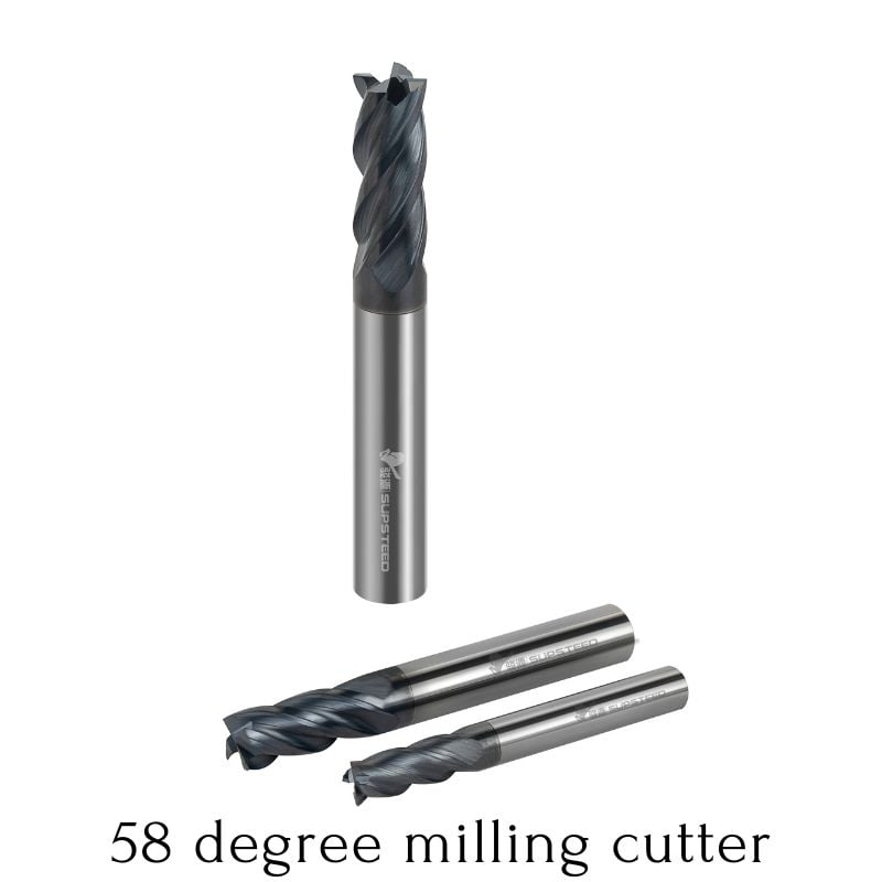
The square end mill features a flat bottom with sharp, 90-degree corners where the peripheral flutes meet the face. This design facilitates simultaneous peripheral and face cutting. During facing operations, the flat profile allows for uniform load distribution across the entire tool tip. The sharp corners create precise, perpendicular intersections between walls and floors. The straight or helical flutes along the side of the tool handle the primary material removal during side milling, pulling chips up and away from the cutting zone.
When you engage a square end mill radially, the cutting forces are distributed along the engaged length of the flute. This allows machinists to utilize the entire flute length for deep axial cuts. The core diameter of a square tool remains consistent all the way down to the cutting tip, providing maximum rigidity and resistance to deflection under heavy chip loads.
A ball nose end mill terminates in a hemispherical cutting tip. The cutting radius of this tool is exactly equal to half of its total diameter. This continuous curve means the tool lacks sharp corners entirely. The engagement angle changes constantly depending on the depth of cut and the contour of the workpiece. This spherical geometry allows the tool to machine complex, multi-axis curves without digging into the material or leaving sharp witness marks.
Unlike a square tool, the core diameter of a ball nose tapers down to a single point at the tip. This structural difference makes the tip of a ball nose inherently weaker than the flat bottom of a square tool. When programming a ball nose, you must account for this varying geometry, as the tool behaves differently depending on how far up the radius the material engages.
The most critical mechanical difference between these tools lies in the Surface Footage per Minute (SFM). SFM dictates the actual speed at which the cutting edge moves through the material. On a square tool, the SFM is relatively consistent across the outer diameter. If you are running a half-inch square end mill at 10,000 RPM, the outer edge is cutting at roughly 1,300 SFM.
On a ball nose tool, the SFM varies along the radius. At the exact dead center of a ball nose tool, the effective cutting diameter is zero. Consequently, the surface speed at the tip is also zero. When the dead center engages the material, it rubs rather than cuts. This rubbing generates excessive heat, accelerates tool wear, and degrades the surface finish. Machinists must program toolpaths that keep the tool engaged on the side of the ball, rather than plunging straight down or cutting with the dead center.
Square geometries dominate standard milling operations due to their aggressive material removal capabilities and ability to create fundamental geometric features. They are the workhorses of any CNC machine shop.
Despite their efficiency, square end mills have specific mechanical vulnerabilities that programmers must manage.
Spherical geometries are specialized tools designed for finishing operations and complex surface generation where square tools fail. They are heavily utilized in mold making, aerospace, and medical device manufacturing.
Ball nose tools require careful programming to avoid their inherent mechanical disadvantages.
Evaluating a square vs ball nose end mill requires analyzing how their geometries perform under specific machining metrics. The choice directly impacts production speed, part quality, and tooling budgets.
Square end mills achieve vastly superior MRR during roughing and pocketing. They permit aggressive feed rates and deep axial cuts. A standard dynamic milling toolpath utilizes the full flute length of a square tool to peel away material rapidly. You can calculate MRR by multiplying the radial depth of cut (RDOC), axial depth of cut (ADOC), and the feed rate in inches per minute (IPM). Because square tools can handle a much larger ADOC, their MRR is exponentially higher.
Ball nose tools require lighter, multi-pass strategies. Their spherical shape limits the axial depth of cut, forcing the machine to take many shallow passes to remove the same volume of material. If you attempt to push a ball nose tool with the same ADOC as a square tool, the varying chip load will cause severe chatter or snap the tool entirely.
Floor finish with square end mills depends heavily on spindle tramming and tool runout. A properly trammed machine yields a mirror finish on flat floors rapidly, requiring only a single pass with a wide stepover (up to 70% of the tool diameter).
Surface finish with ball nose end mills relies on the mathematical relationship between the tool radius, the stepover distance, and the resulting scallop height. Scallops are the tiny ridges left between parallel toolpaths. Tighter stepovers reduce scallop height and improve the finish, but they exponentially increase cycle time. Programmers must calculate the exact stepover required to meet the blueprint's surface roughness (Ra) callout without wasting hours of machine time.
Square tools distribute cutting loads evenly across the tip width during facing, but they wear at the sharp corners first during heavy radial engagement. Once the corner rounds over, the tool loses its ability to cut sharp 90-degree features and begins to push the material rather than shear it.
Ball nose tools often wear at the specific engagement angle of the contour. If you are surfacing a 30-degree slope, the tool will develop a wear band exactly at that contact point. If programmed poorly and forced to cut with the dead center, the tip will degrade rapidly due to heat and friction, while the rest of the flute remains pristine.
Table: Tool Geometry Performance Summary
| Performance Metric | Square End Mill | Ball Nose End Mill |
|---|---|---|
| Material Removal Rate (MRR) | Excellent for flat/side milling | Poor for bulk material removal |
| Flat Floor Finish | Excellent (requires proper tramming) | Poor (requires microscopic stepovers) |
| 3D Contouring | Leaves severe stair-steps | Excellent smooth transitions |
| Corner Wear Resistance | Low (sharp corners chip easily) | High (continuous radius distributes stress) |
| Effective Cutting Speed at Tip | High and consistent | Zero at dead center (rubbing) |
Machinists are not strictly limited to sharp squares or full spheres. Corner radius end mills, often called bull nose end mills, provide a strategic hybrid solution that solves the primary weaknesses of both tools.
A corner radius end mill features a flat bottom like a square tool, but the sharp 90-degree corners are replaced with a specific radius. This radius can range from a few thousandths of an inch (e.g., 0.015") to nearly half the tool diameter. This design blends the flat-cutting efficiency of a square tool with the corner strength of a ball nose.
Adding a radius to a square end mill drastically increases tool strength. The radius eliminates the stress concentration point found on sharp corners. This structural reinforcement allows machinists to push the tool with heavier feed rates and deeper cuts than both standard square and ball nose tools. The rounded corner resists chipping in hard materials like Inconel, 4140 steel, and titanium, significantly extending tool life during heavy roughing operations.
Bull nose tools frequently replace square end mills for roughing operations where a sharp internal corner is not required. They also replace ball nose tools for shallow contouring and semi-finishing on slightly curved surfaces. In these overlapping applications, bull nose mills achieve significantly higher feed rates and deeper axial depths of cut compared to ball nose tools, drastically reducing cycle times without sacrificing tool life.
Selecting the optimal tool requires a systematic approach based on part requirements, machining stages, and equipment capabilities. Guessing leads to broken tools and scrapped parts.
Table: CAM Strategy Alignment
| Tool Geometry | Primary CAM Toolpath | Engagement Strategy |
|---|---|---|
| Square End Mill | Dynamic OptiRough / Adaptive Clearing | High ADOC, Low RDOC (Chip Thinning) |
| Ball Nose End Mill | Scallop / Waterline / Raster | Low ADOC, Tight Stepover |
| Bull Nose End Mill | Traditional Pocketing / High-Feed Roughing | Moderate ADOC, High Feed Rate |
Transitioning between different tool geometries introduces specific machining risks that require proactive mitigation on the shop floor.
A: While technically possible, using a flat-bottomed tool for 3D contouring creates a severe stair-step effect on the workpiece. This requires extensive, time-consuming secondary finishing operations to smooth out the surface. Ball nose tools are the correct choice for 3D contours.
A: The dead center of a ball nose tool has an effective cutting diameter of zero, meaning its surface speed is also zero. When this center point engages the material, it rubs and generates extreme heat rather than shearing material, leading to rapid tip wear.
A: Stepover is calculated based on the tool radius and the maximum allowable scallop height. Tighter stepovers produce smaller scallops and smoother finishes but significantly increase the total machining cycle time. CAM software usually calculates this automatically based on your desired finish.
A: Yes, corner radius (bull nose) end mills are generally superior for heavy roughing. The added radius removes the fragile 90-degree corner, distributing cutting forces and preventing chipping. This allows for more aggressive feed rates and longer tool life in hard materials.
A: BUE occurs when machining gummy materials like aluminum. Heat and pressure cause the workpiece material to weld to the sharp cutting edge. Poor chip evacuation, inadequate coolant flow, and incorrect tool coatings exacerbate this issue, eventually leading to tool failure.
A: You can, but it is highly inefficient. Because the spherical tip only contacts the flat floor at a microscopic point, you must program extremely tight stepovers to achieve a flat surface. A square tool can clear the same flat floor in a fraction of the time.