English
- All
- Product Name
- Product Keyword
- Product Model
- Product Summary
- Product Description
- Multi Field Search

Views: 0 Author: Site Editor Publish Time: 2026-08-27 Origin: Site

Dealing with material waste and secondary finishing costs is a constant battle when routing engineered sheet goods. Edge fuzz, burn marks, and veneer tear-out destroy project margins and consume hours of manual sanding. Unlike solid hardwoods, engineered materials present distinct machining challenges. The abrasive adhesives used in MDF rapidly degrade cutting edges. Meanwhile, the alternating grain directions in plywood veneers invite severe delamination under rotational cutting forces.
Achieving a zero-defect finish directly depends on moving away from trial-and-error setups. You must match tool geometry, carbide grade, and chipload to the specific material composition. A predictable tooling strategy eliminates scrap and ensures parts come off the machine ready for assembly. By understanding how different flute designs interact with laminated surfaces and abrasive cores, operators can consistently produce flawless cuts on both faces of the material.
A clean finish on the CNC router is defined by strict success criteria. Parts must exhibit zero top or bottom veneer tear-out, absolutely no edge fuzz, zero burn marks, and perfect dimensional accuracy. Achieving this requires overcoming the inherent vulnerabilities of engineered wood products. Plywood mechanics involve alternating layers of wood grain pressed together under high pressure. When a rotating cutting edge strikes these layers, it exerts lifting or pressing forces. If the tool pulls against the grain of a thin surface veneer, delamination occurs instantly, ruining the sheet.
Material variance plays a massive role in cut quality. Premium materials like Baltic Birch feature void-free cores and thick, consistent veneers that machine predictably. The uniform density allows the cutting tool to maintain a constant chip load. In contrast, big-box store plywood often hides massive core voids, overlapping internal layers, and inconsistent glue distribution. When a router bit hits an internal void, the sudden lack of backing support causes the adjacent veneer to splinter, regardless of how sharp the tool is. You cannot out-machine poor material quality. The sudden drop in cutting resistance also causes the spindle to lunge slightly, inducing chatter marks on the cut edge.
MDF and melamine present entirely different realities on the machine bed. MDF is manufactured using dense wood fibers bound together with urea-formaldehyde resins. This binder is exceptionally abrasive. Furthermore, the manufacturing process creates a hardened outer crust on MDF sheets, while the inner core remains slightly softer. When standard high-speed steel (HSS) cutting edges engage with MDF, the resins cause rapid micro-fracturing along the cutting edge. The hardened outer crust specifically creates a wear notch on the flute at the exact depth of cut. As the edge degrades, the tool stops shearing the material and begins rubbing against it. This friction generates extreme heat, leading to burnt edges, localized material expansion, and severe edge fuzz that requires heavy sanding to remove.
Selecting the correct flute geometry dictates where the cutting forces are directed. The goal is always to shear the material toward the center of the sheet, preventing the fragile outer faces from blowing out. Choosing the right cnc router wood cutting tools requires analyzing the specific requirements of your current operation, the thickness of the material, and the holding power of your vacuum table.
Up-cut geometries feature flutes that twist upward, pulling chips out of the cut channel toward the spindle. This provides excellent chip evacuation, keeping the tool cool and preventing the recutting of waste material. The outcome is a perfectly clean bottom edge, as the cutting force pulls the material up against the spoilboard. However, this same upward force guarantees severe tear-out on the top veneer. Up-cut bits are ideal for blind pockets, drilling operations, or cutting materials where the top surface finish is irrelevant. They also require robust workholding, as the lifting action will pull small parts right off a weak vacuum table.
Down-cut bits reverse the flute direction, pushing chips downward into the cut path. This downward shearing action leaves a flawless top edge, pressing the veneer firmly against the core. The trade-off is poor chip evacuation. Because the chips are packed into the bottom of the cut, heat builds up rapidly. Down-cut bits risk bottom tear-out and require significantly slower feed rates to prevent tool breakage. They are the optimal choice for shallow dados, cutting thin flexible materials, or routing the top surface of MDF where you need to preserve a delicate laminate or melamine face.
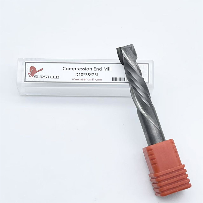
For sheet goods requiring perfect faces on both sides, compression router bits serve as the ultimate hybrid solution. These tools combine an up-cut section at the tip with a down-cut section along the rest of the cutting length. This geometry directs all cutting forces toward the center of the material, compressing the top and bottom veneers simultaneously. The outcome is a pristine finish on both faces, eliminating the need for secondary edge sanding.
The primary implementation risk involves the up-shear length. The up-cut portion at the tip of the bit is usually between 0.200 and 0.250 inches long. For the compression effect to work, your first pass must be deeper than this up-shear length. If you take a shallow first pass of 0.125 inches, only the up-cut portion engages the material, acting purely as an up-cut bit and completely ruining the top veneer. For shallow dados, operators must use specialized mortise compression bits, which feature a much shorter up-shear length of around 0.100 inches.
To properly execute a cut with a compression tool, operators should follow a specific sequence:
The abrasive nature of engineered woods demands rigorous tool material selection. High-Speed Steel (HSS) should be entirely dismissed for CNC sheet good production. It lacks the rigidity to prevent deflection and loses its edge almost immediately when cutting MDF binders. Solid micro-grain carbide is the mandatory baseline. The micro-grain structure provides the heat tolerance and stiffness required for consistent production. The cobalt binder used in high-quality carbide prevents the cutting edge from chipping under the heavy impact loads of routing plywood cores.
Insert tooling presents a strong return on investment for high-volume shops. Replaceable carbide insert bits allow operators to swap dull cutting edges directly on the machine without altering the tool diameter. This eliminates the need to update tool libraries in CAM software after sharpening, ensuring dimensional accuracy remains locked in over hundreds of sheets. Insert bodies are balanced for high RPMs, and the carbide knives are often thicker than the flutes on solid tools, providing excellent heat dissipation.
Polycrystalline Diamond (PCD) tooling represents the ultimate high-production solution for continuous MDF and melamine nesting. PCD offers exceptional scalability, delivering 50 to 100 times the lifespan of standard solid carbide. The diamond particles are sintered together under extreme pressure, creating an edge that simply ignores the abrasive urea-formaldehyde resins in MDF. The trade-offs include a high initial capital cost and extreme brittleness. PCD edges will shatter instantly if they strike a staple, screw, or foreign object hidden inside cheap plywood cores. Therefore, PCD is strictly reserved for clean, predictable materials.
Specialized coatings like Zirconium Nitride (ZrN) or Titanium Aluminum Nitride (TiAlN) are frequently marketed to extend tool life. While these coatings legitimately reduce friction and prevent pitch build-up when cutting resin-heavy woods, operators should maintain a skeptical stance on exaggerated lifespan claims. In highly abrasive MDF, the substrate material matters far more than the microscopic coating layer. Once the coating wears off the very tip of the cutting edge, the underlying carbide is exposed to the abrasive binders anyway.
Comparison of Tool Materials for Routing Engineered Woods
| Tool Material | Edge Retention | Shock Resistance | Ideal Application |
|---|---|---|---|
| High-Speed Steel (HSS) | Very Low | High | Softwoods, plastics (Not recommended for MDF/Plywood) |
| Solid Micro-Grain Carbide | High | Moderate | General plywood, MDF, and melamine routing |
| Carbide Insert Tooling | High | Moderate | High-volume routing requiring consistent tool diameters |
| Polycrystalline Diamond (PCD) | Extreme | Very Low | Continuous industrial nesting of abrasive MDF/Melamine |
A flawless finish is mathematically derived from proper chip evacuation. The industry-standard formula for this is Chipload. Chipload dictates the physical size of the wood chip removed by each cutting flute per revolution. The formula is: Feed Rate = RPM × Number of Flutes × Chipload. If the chipload is too low, the tool rubs against the material instead of shearing it, causing extreme heat and burning. If the chipload is too high, the machine experiences chatter, leading to poor edge quality and broken tools.
For example, if you are running a 2-flute 3/8-inch tool and targeting a chipload of 0.015 inches at 18,000 RPM, your required feed rate is 540 inches per minute (IPM). If your machine cannot physically move at 540 IPM without shaking violently, you cannot simply lower the feed rate without also lowering the RPM. Failing to balance these numbers results in dust rather than chips. Dust is a primary indicator that you are recutting material, generating friction, and destroying the temper of your carbide.
Managing chipload depends heavily on your spindle type and RPM limitations. Industrial VFD spindles offer precise RPM control, allowing operators to dial in the exact speed needed for a specific feed rate. Hobbyist and prosumer setups often rely on 5-speed routers. These routers typically have a minimum speed of 10,000 RPM. To maintain a proper chipload at 10,000 RPM, the machine must move rapidly. If the hobby CNC lacks the rigidity to move that fast, the operator is forced to cut at a low chipload, which inevitably dictates MDF burning and rapid tool dulling.
The common dilemma of cutting 3/4-inch plywood highlights the difference between single-pass and multi-pass strategies. Single-pass cutting requires high machine rigidity and significant spindle horsepower. It maximizes the effectiveness of compression bits by engaging both the up-cut and down-cut geometries simultaneously, ensuring a perfect finish and rapid cycle times. Multi-pass cutting reduces the load on the spindle but severely complicates chip evacuation. The hobbyist reality often involves taking 3 to 4 passes on 3/4-inch material. This traps chips in the deep trench, increases heat friction, and frequently results in stepped edges where the tool deflects slightly on each subsequent pass.
Managing heat and deflection is critical. Tool deflection occurs when the lateral cutting forces bend the bit during deep passes. This bending causes the stepped edges seen in multi-pass cuts. Optimizing the length-of-cut (LOC) to closely match the material thickness minimizes this risk. Using a bit with a 1-inch LOC to cut 3/4-inch material provides far more rigidity than using a bit with a 2-inch LOC, drastically reducing vibration and deflection.
Common Cut Defects and Feed/Speed Adjustments
| Defect Observed | Primary Cause | Required Adjustment |
|---|---|---|
| Burn marks on cut edge | Chipload too low (rubbing) | Increase feed rate or decrease RPM |
| Heavy chatter marks | Chipload too high or machine flex | Decrease feed rate or increase RPM |
| Top veneer tear-out | Up-cut geometry or shallow first pass | Use down-cut/compression, increase pass depth |
| Stepped edges on multi-pass | Tool deflection | Use shorter LOC tool, leave roughing allowance |
Even the most expensive cutting tools will leave a terrible finish if the machine infrastructure is compromised. Vibration and chatter are the enemies of a clean cut. If the machine gantry lacks rigidity, or if the spindle exhibits runout (wobble), the cutting edge will hammer against the material rather than slicing it. This micro-hammering shatters delicate plywood veneers and leaves a washboard texture on MDF edges. Spindle runout should be checked regularly with a dial indicator; anything over 0.001 inches will drastically reduce tool life and cut quality.
Securing warped plywood introduces severe implementation realities. Bowed material refuses to lay flat on the spoilboard. This makes it impossible to maintain consistent cut depths. If the material bows upward, a compression bit's up-shear section may rise above the bottom veneer, causing massive tear-out. Furthermore, unsupported bowed sections will vibrate violently during the cut, inducing chatter that transfers directly to the finished edge.
Mitigation strategies vary by machine class. Industrial vacuum tables are highly effective but require massive CFM (Cubic Feet per Minute) generation to pull through porous MDF spoilboards and flatten warped sheets. Operators must regularly surface their spoilboards to remove cut grooves, as these grooves cause vacuum leaks that reduce holding power. When cutting small parts that tend to shift, operators use an onion skinning technique. This involves cutting down to within 0.020 inches of the spoilboard, leaving a thin skin of material to maintain vacuum pressure, and then returning for a final pass to free the part.
Mechanical and hobbyist fastening methods require more manual intervention. Using composite nails, edge clamping, or heavy weights can force the material down. For smaller parts, the painter's tape and cyanoacrylate (CA) glue trick provides excellent lateral and vertical holding power without obstructing the tool path. Proper spoilboard preparation is non-negotiable for consistent results.
Follow these steps to maintain a reliable spoilboard surface:
A: Solid micro-grain carbide or Polycrystalline Diamond (PCD) tools are essential to combat the highly abrasive urea-formaldehyde binders in MDF. Use down-cut bits if only the top surface finish matters, as they prevent edge fuzz. For full-depth through-cuts requiring clean top and bottom edges, compression bits are the optimal choice.
A: Use compression bits when cutting materials that require a flawless, chip-free edge on both the top and bottom faces simultaneously. They are the industry standard for routing double-sided veneered plywood, double-sided melamine, and laminated particleboard, as they push cutting forces toward the center of the core.
A: Yes, material quality heavily dictates the finish. Big-box store plywood often contains hidden core voids, overlapping internal layers, and cheap, thin veneers. When a bit hits a void, the lack of backing causes the veneer to splinter. For flawless results, use premium materials like Baltic Birch or high-grade cabinet plywood.
A: Burning is caused by friction, which occurs when the chipload is too low. This happens due to running feed rates too slowly, setting spindle RPMs too high, or using dull bits. The tool rubs against the material instead of shearing it. Fixed-speed routers are particularly prone to this issue.
A: This depends entirely on machine rigidity, spindle horsepower, and tool diameter. Heavy industrial machines routinely cut 3/4" plywood in a single pass at high speeds. Hobbyist machines typically require 3 to 4 passes to prevent stalling the spindle, though this increases the risk of heat buildup and stepped edges.
A: Veneer tear-out is primarily caused by using up-cut geometries that pull the fragile top layer away from the core. Other contributing factors include dull cutting edges, incorrect spindle speeds, excessive vibration from poor workholding, or cutting cheap plywood with internal core voids that fail to support the veneer.
A: Lifespan varies based on chipload optimization and material density, but solid carbide bits generally process between 30 to 50 sheets of MDF before edge degradation causes unacceptable fuzzing. Running optimal feeds and speeds maximizes this lifespan, while running at low chiploads will burn out the carbide much faster.