Please Choose Your Language
- All
- Product Name
- Product Keyword
- Product Model
- Product Summary
- Product Description
- Multi Field Search

Views: 0 Author: Site Editor Publish Time: 2026-08-25 Origin: Site

Product designers and procurement engineers constantly balance Material Removal Rates (MRR) with tool wear, machining time, and part accuracy. Selecting the wrong machining process or tooling strategy leads to increased scrap rates, poor surface finishes, and inflated production costs. Understanding the mechanics of what is end milling solves these production bottlenecks. It helps optimize Design for Manufacturability (DFM), evaluate machining partners, and ensure efficient production runs. This guide breaks down the technical realities, tooling variables, and operational risks of the process. We will look at how cutter geometry, feed rates, and tool holding directly impact your final part tolerances and surface finishes.
Defining the baseline capabilities of end milling establishes exactly when it is the correct technical solution for a specific part geometry. Engineers must understand the fundamental kinematics of the process to design parts that can be manufactured efficiently. End milling utilizes a cylindrical cutting tool equipped with multiple cutting edges on both its periphery and its tip. As the machine spindle rotates the tool at high speeds, the machine feeds the workpiece into the cutter or moves the cutter across the stationary workpiece.
The kinematic mechanics of this operation allow for simultaneous lateral and vertical material removal. The cutter engages the material along the X and Y axes for lateral cuts, while also possessing the ability to move along the Z axis for depth. This dual-action capability generates both perpendicular and tangential cutting forces. The tangential forces shear the material away in the form of chips. The perpendicular forces dictate the structural rigidity required from the machine tool setup to prevent deflection.
Distinguishing end milling from standard drilling is a basic requirement for process planning. Drill bits are designed exclusively to cut axially, plunging straight down to create cylindrical holes. They only feature cutting edges at their conical tip. End mills feature flutes that run up the sides of the tool body. This allows them to cut laterally across a surface. While certain end mills can plunge like a drill, their primary function lies in executing complex profiling, deep pocketing, and precise slotting operations that a standard drill bit cannot perform.
This lateral cutting capability makes end milling the backbone of multi-axis machining. The integration of end mills across different machine platforms dictates the complexity of parts you can produce:
Reducing multiple part setups through multi-axis integration directly minimizes tolerance stacking errors and accelerates production timelines.
Executing a successful end milling process requires mastering the interaction between the cutting tool and the workpiece material. The strategy chosen for how the tool engages the material profoundly impacts the final part quality and the longevity of the tooling.
Climb milling, also known as down milling, occurs when the cutter rotates in the same direction as the feed rate. The cutting edge enters the material at maximum chip thickness and exits at zero thickness. This approach yields a superior surface finish, lower heat generation transferred into the workpiece, and extended tool life. The cutting forces naturally push the workpiece down into the fixture, enhancing stability. Climb milling demands rigid machinery equipped with ballscrews that have zero backlash. If the machine has play in its axes, the tool can grab the material and pull itself forward, leading to catastrophic tool breakage or scrapped parts.
Conventional milling, or up milling, reverses this dynamic. The cutter rotates against the direction of the feed. The cutting edge starts at zero chip thickness and rubs against the material until enough pressure builds to shear a chip, exiting at maximum thickness. While this rubbing action increases tool wear and generates more heat, conventional milling remains necessary for specific use cases. It is the preferred method when roughing cast iron, machining forgings with hard surface scales, or operating older manual machines with inherent backlash. The primary drawback is that the cutting forces tend to lift the workpiece out of the vise, requiring heavy-duty workholding solutions.
Comparison of Milling Strategies| Feature | Climb Milling (Down Milling) | Conventional Milling (Up Milling) |
|---|---|---|
| Chip Thickness | Starts maximum, ends at zero | Starts at zero, ends maximum |
| Cutting Forces | Pushes part down into fixture | Lifts part up from fixture |
| Surface Finish | Excellent (less recutting of chips) | Poor to Fair (tool rubs before cutting) |
| Machine Requirement | Requires zero backlash (ballscrews) | Tolerates backlash (older machines) |
| Tool Wear | Lower (heat transfers to chip) | Higher (heat transfers to tool/part) |
Beyond cutting direction, operators must strictly control machining parameters. The relationship between spindle speed (RPM) and feed rate (inches or millimeters per minute) dictates the efficiency of material removal. Spindle speed is determined by the surface footage recommended for the specific tool material and workpiece material combination. Feed rate is calculated based on the desired chip load.
Chip load, or feed per tooth, represents the physical thickness of the material removed by a single cutting edge in one revolution. Calculating the optimal chip thickness ensures efficient heat evacuation. Most of the heat generated during milling should be carried away by the chip itself. If the chip load is too light, the tool rubs rather than cuts, causing rapid heat buildup and premature edge dulling. If the chip load is too heavy, the cutting edges overload and snap.
Depth of cut must be balanced across two dimensions: axial (step-down) and radial (step-over). Axial depth refers to how deep the tool plunges into the material along the Z-axis. Radial depth dictates how much of the tool's diameter engages the material laterally. Maximizing MRR requires balancing these two metrics. Heavy axial cuts typically require light radial step-overs to prevent catastrophic tool failure, a strategy frequently utilized in modern high-efficiency toolpaths.
Tool holding technology plays a massive role in process mechanics. How the end mill is secured to the spindle directly affects runout—the degree to which the tool rotates off its true center axis. Standard ER collets provide adequate holding force for general operations but introduce slight runout. For high-precision applications, shrink-fit holders or hydraulic chucks are utilized. These advanced holders grip the tool shank with immense, uniform pressure, reducing runout to mere microns. Minimizing runout ensures that every flute takes an equal chip load, which directly extends tool life and maintains strict dimensional accuracy on the machined part.
Matching tool geometry to specific material properties and desired part features dictates exactly what features can be produced and how fast the machine can run. The physical shape, material composition, and flute count of the end mill are the primary variables you control.
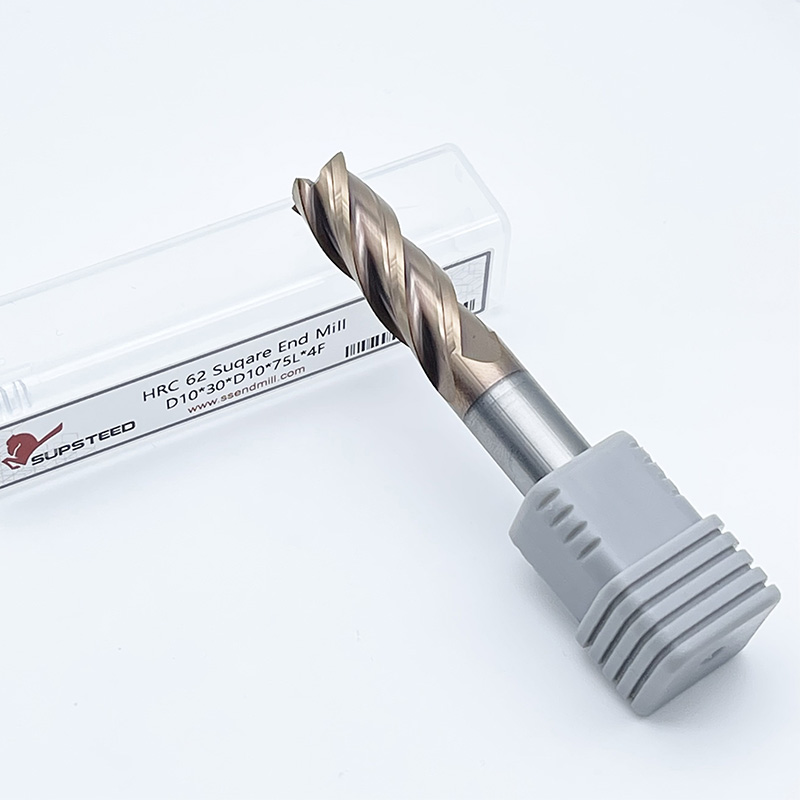
End mill geometries are engineered for distinct applications. Square end mills are the industry standard for general-purpose machining. They feature sharp 90-degree corners at the tip, making them ideal for cutting flat-bottomed slots, precise pockets, and sharp internal corners. Ball nose end mills feature a fully rounded tip. They are used for 3D contouring, complex surfacing, and machining fillets where a sharp corner would create a stress riser. Corner radius end mills, often called bull nose cutters, blend these two designs. They feature a flat bottom with radiused corners. This geometry distributes cutting forces more evenly across the tool edge, significantly reducing the risk of chipping and extending tool life in high-stress roughing applications.
Roughing end mills, commonly referred to as corncob cutters, feature serrated cutting edges. These serrations break the chips into much smaller pieces during rapid material removal. Smaller chips evacuate faster and require less machine horsepower to shear, making roughing end mills ideal for heavy, deep passes in tough materials like 4140 steel or cast iron.
A strict distinction exists between center-cutting and non-center-cutting geometries. Center-cutting end mills feature flutes that extend completely to the center of the tool face. This allows the tool to plunge straight down into solid material exactly like a drill bit. Non-center-cutting end mills have a small void or relief at the center of the tip. They cannot plunge straight down. Entering the material requires a pre-drilled pilot hole, a ramping toolpath, or helical interpolation. Non-center-cutting tools often feature a thicker, stronger core, making them highly effective for heavy peripheral milling where plunging is not required.
When machining softer materials like plastics, composites, or wood, material-specific flute dynamics become paramount. Up-cut flutes pull chips up and out of the cut, which clears deep slots but can cause delamination or tear-out on the top surface of fibrous materials. Down-cut flutes push chips downward, leaving a pristine top edge but complicating chip evacuation. Compression end mills combine both, pulling up from the bottom and pushing down from the top, ensuring clean edges on both sides of a laminated workpiece.
Flute count directly impacts chip evacuation and core strength. A 2-flute or 3-flute end mill features wide, deep flute valleys. This high volume of open space allows for maximum chip clearance, which is mandatory when cutting gummy materials like aluminum or plastics that tend to melt and pack into the flutes. Conversely, 4-flute, 5-flute, or higher-count end mills have shallower valleys but a much thicker central core. The higher core strength resists deflection, and the increased number of cutting edges per revolution allows for faster feed rates and superior surface finishes. These higher flute counts are optimal for harder materials like steel, stainless steel, and titanium.
Tool materials and applied coatings further define performance limits. High-Speed Steel (HSS) is affordable and highly shock-resistant, suitable for manual machines or low-volume aluminum work. Solid carbide is the standard for professional production. It is significantly harder and more rigid than HSS, allowing for much faster cutting speeds and longer life, though it is more brittle. Cobalt falls between the two, offering better heat resistance than HSS.
Common End Mill Coatings and Applications| Coating Type | Properties | Best For |
|---|---|---|
| TiN (Titanium Nitride) | General purpose, adds lubricity, gold color. | Aluminum, Brass, low-carbon steels. |
| TiCN (Titanium Carbonitride) | Harder than TiN, lower friction coefficient. | Cast iron, stainless steel, abrasive plastics. |
| TiAlN (Titanium Aluminum Nitride) | Forms an aluminum oxide layer under high heat. | High-temp alloys, dry machining of steels. |
| AlTiN (Aluminum Titanium Nitride) | Higher aluminum content than TiAlN, extreme heat resistance. | Titanium, Inconel, hardened tool steels. |
| Diamond (CVD/PVD) | Maximum hardness, extreme abrasion resistance. | Carbon fiber, fiberglass, high-silicon aluminum. |
Mapping specific part features to the appropriate CNC end milling technique ensures efficient programming and execution. Each operation presents unique physical challenges that require specific toolpath strategies.
Slot milling involves cutting enclosed channels or grooves into the workpiece. The primary challenge here is chip evacuation. Because the tool is engaged on both sides simultaneously (180-degree radial engagement), chips easily become trapped, leading to recutting, heat buildup, and broken tools. To combat this, programmers utilize trochoidal toolpaths. Instead of driving the tool straight down the slot, the machine drives the tool in continuous circular motions, taking light radial bites. This keeps the tool engaged for shorter durations, allows chips to escape, and drastically reduces cutting forces.
Pocket milling focuses on clearing large internal volumes of material. Traditional pocketing involved heavy radial step-overs and shallow axial depths. Modern High-Efficiency Milling (HEM) strategies reverse this. HEM utilizes the entire flute length of the end mill (deep axial cuts) combined with very light radial step-overs. This distributes tool wear evenly across the entire cutting edge rather than concentrating it at the tip, maximizing tool life and allowing for incredibly fast feed rates.
Profiling involves machining the exterior or interior boundaries of a part to achieve final dimensions. The focus during profiling is maintaining strict dimensional accuracy across the entire Z-axis depth. If the tool deflects during a deep profiling pass, the resulting wall will be tapered rather than perfectly vertical. Spring passes—running the same finishing toolpath twice without changing dimensions—are used to eliminate residual deflection and ensure a perfectly straight wall.
Facing operations create large, flat surfaces. While end mills can perform facing, choosing the right tool diameter is critical. A small end mill requires dozens of passes to face a large block, increasing cycle time and leaving visible step-over marks. For large surfaces, a dedicated face mill with indexable carbide inserts is preferred. For smaller parts or tight clearance areas, a large-diameter solid carbide end mill provides an excellent, flat finish.
Plunging and ramping are techniques for entering the raw material safely. Plunging drives the tool straight down along the Z-axis, requiring a center-cutting end mill. Ramping enters the material at a shallow angle, moving simultaneously in the X/Y and Z axes. Ramping reduces the axial load on the tool tip, allows non-center-cutting tools to enter solid material, and facilitates better chip evacuation during the initial entry phase.
Determining whether end milling is the most viable process for a specific production run requires analyzing several conceptual trade-offs. Engineers must weigh the required precision against the associated manufacturing costs.
High-precision end milling capable of holding tight tolerances (such as ±0.0005 inches) demands meticulous setup. Achieving this level of accuracy requires slower feed rates to prevent deflection, specialized high-precision tooling, rigid workholding, and frequent tool changes to ensure sharp edges. These factors inherently increase the cycle time and the overall cost per part. If a part functions perfectly well with a standard ±0.005-inch tolerance, specifying tighter tolerances unnecessarily inflates production budgets.
Surface finish capabilities, measured in Roughness Average (Ra), dictate process selection. End milling can achieve excellent surface finishes, often down to 16-32 microinches Ra with proper finishing passes and sharp carbide tools. Understanding the physical limits of the milling process is necessary. If a part requires a mirror-like cosmetic finish or a critical sealing surface with an Ra of 4 or 8, end milling alone will not suffice. Identifying these requirements early allows engineers to plan for secondary operations, such as cylindrical grinding, lapping, or electropolishing.
Material machinability heavily influences production viability. The hardness, tensile strength, and thermal conductivity of the workpiece material dictate tool life and machining time. Free-machining brass or 6061 aluminum can be milled at extremely high velocities with minimal tool wear. Machining Inconel or Grade 5 Titanium requires slow spindle speeds, heavy coolant application, and frequent tool replacements due to their tendency to work-harden and their poor thermal conductivity, which traps heat at the cutting edge.
Scalability must be assessed. For rapid prototyping and low-volume production, CNC end milling offers high flexibility with relatively low setup costs. A machinist can program a part and cut it from bar stock in hours. For high-volume production scaling into tens of thousands of units, the cycle time of end milling may become a bottleneck. In these scenarios, alternative processes like die casting, forging, or extrusion might become more economical, with end milling reserved only for secondary finishing operations on critical mating surfaces.
End Mill Flute Count Application Guide| Flute Count | Primary Advantage | Chip Evacuation | Ideal Workpiece Materials |
|---|---|---|---|
| 2 Flute | Maximum chip clearance | Excellent | Aluminum, Plastics, Wood, Brass |
| 3 Flute | Balance of clearance and core strength | Very Good | Aluminum alloys, Non-ferrous metals |
| 4 Flute | High core strength, better finish | Moderate | Carbon Steel, Alloy Steel, Cast Iron |
| 5+ Flute | Maximum feed rates, superior Ra finish | Poor (requires small chips) | Titanium, Stainless Steel, Hardened Alloys |
When evaluating a vendor for outsourced production, specific criteria indicate their capability to handle complex milling tasks. Look for manufacturing partners who utilize advanced CAM software capable of generating dynamic, high-efficiency toolpaths. In-house tool presetting equipment demonstrates a commitment to precise tool length offsets, reducing setup errors. Strict coolant management systems ensure thermal stability during long runs. Robust CMM (Coordinate Measuring Machine) inspection capabilities are mandatory to verify that the final milled parts meet all geometric dimensioning and tolerancing (GD&T) callouts.
Even with optimal tooling and programming, the end milling process carries inherent physical risks. Identifying these common failure modes allows operators to implement effective mitigation strategies before parts are scrapped.
Tool deflection is a primary concern, especially when using long, thin end mills. Deflection is the physical bending of the cutter under lateral cutting forces. When the tool bends away from the workpiece, it leaves excess material behind, resulting in tapered walls and out-of-tolerance dimensions. Mitigation requires maximizing tool rigidity. Operators should select tools with the largest possible core diameter and the shortest flute length necessary to reach the required depth. Optimizing radial engagement by taking lighter step-overs reduces the lateral pressure exerted on the tool.
Chatter and vibration destroy surface finishes and shatter carbide tools. Chatter occurs when the frequency of the cutting edges striking the material aligns with the resonant frequency of the machine, tool, or workpiece. This harmonic resonance creates violent vibrations. Mitigation involves disrupting these harmonics. Adjusting spindle speeds slightly up or down can break the resonance. Utilizing variable-helix or variable-pitch end mills—where the flutes are spaced at unequal angles—prevents harmonics from building up. Ensuring maximum workpiece rigidity through proper fixturing and minimizing tool overhang are critical steps.
Thermal damage and work hardening pose severe risks when machining specific alloys. Excessive heat buildup can alter the metallurgical properties of the part, warping thin sections or burning the surface. In materials like 304 stainless steel or titanium, rubbing a dull tool against the surface causes the material to work-harden, creating a hardened crust that destroys the next tool that tries to cut it. Mitigation requires strict thermal management. Proper application of high-pressure flood coolant, Minimum Quantity Lubrication (MQL), or targeted air blasts clears hot chips away from the cutting zone. Maintaining a correct, aggressive chip load ensures the tool cuts beneath any work-hardened layer and transfers heat into the chip rather than the workpiece.
To improve your current manufacturing outcomes and reduce tooling costs, implement the following steps on your shop floor:
A: End mills can machine soft plastics, wood, composites, and non-ferrous metals like aluminum and brass. With the correct carbide substrates and advanced coatings, they effectively cut tough materials like carbon steel, stainless steel, titanium, Inconel, and hardened tool steels.
A: Chip load is calculated by dividing the total feed rate (inches per minute) by the product of the spindle speed (RPM) and the number of flutes on the tool. The formula is: Chip Load = Feed Rate / (RPM × Number of Flutes).
A: Tool breakage is caused by excessive chip load, poor chip evacuation leading to recutting, severe tool deflection, or harmonic chatter. Running a tool at incorrect speeds, using a dull cutter, or failing to clear chips from deep pockets will overload the carbide substrate.
A: No. Plunge cutting straight down into solid material requires a center-cutting end mill, where the cutting edges extend entirely to the center of the tool face. Non-center-cutting end mills require a pilot hole, ramping, or helical toolpaths to enter the material safely.
A: Roughing end mills feature serrated edges that break chips into smaller pieces, allowing for aggressive material removal rates and heavy cuts. Finishing end mills have smooth cutting edges designed to take light, precise cuts, leaving a high-quality surface finish and holding tight tolerances.
A: Tool runout causes the end mill to rotate off its true center axis. This results in uneven chip loads, where one flute does most of the cutting. Runout leads to rapid tool wear, poor surface finishes, chatter, and out-of-tolerance part dimensions.