- All
- Product Name
- Product Keyword
- Product Model
- Product Summary
- Product Description
- Multi Field Search

Views: 0 Author: Site Editor Publish Time: 2026-08-23 Origin: Site
Maximizing Material Removal Rates (MRR) while reducing machine downtime and protecting spindle bearings dictates shop profitability. Machinists and manufacturing engineers frequently conflate specific tooling geometries with CAM-driven toolpath strategies. Misapplying these concepts leads to suboptimal cycle times, accelerated tool wear, blown tooling budgets, and excessive material waste from production errors. Resolving this requires a strict technical distinction between the physical mechanics of high feed end mills and the software-driven kinematics of high efficiency milling. This guide establishes a framework for evaluating which approach aligns with specific machine capabilities, part geometries, and production volumes. We will break down the physics of chip formation and force distribution so you can deploy the correct roughing strategy and optimize your manufacturing workflow.
Establishing standard definitions prevents miscommunication between programmers, operators, and tooling vendors on the shop floor. A common error involves confusing these advanced roughing techniques with traditional High-Speed Machining (HSM). Traditional HSM focuses primarily on elevated spindle speeds and lighter feed rates to achieve surface finish. It does not utilize specific engagement algorithms or specialized cutter geometries to maximize material removal. To optimize roughing cycles, we must separate the physical cutting tool from the software generating its path.
The defining characteristic of this approach is the physical geometry of the cutter itself. These specialized tools feature a unique end profile, typically utilizing a large radius or a multi-radii design. This specific shape creates a very shallow lead angle at the cutting edge, usually between 10 and 15 degrees. Because of this geometry, the tool operates with a very low axial depth of cut (ADOC) combined with an exceptionally high feed rate.
This shallow lead angle fundamentally alters how cutting forces interact with the machine tool. Instead of pushing radially against the side of the tool shank—which causes deflection and chatter—the geometry directs cutting forces axially. The pressure travels straight up through the tool holder and directly into the machine spindle. This axial force vectoring maximizes the inherent rigidity of the CNC machine. It allows for aggressive material removal even in less-than-ideal setups or on older equipment with worn linear guides.
These are purpose-built cutters. They differ entirely from the standard square or corner-radius end mills used in traditional roughing. You cannot execute a true high feed strategy without the correct physical tool geometry. Attempting to run a standard end mill at high feed parameters will instantly snap the tool.
Physical characteristics of these tools include:
Furthermore, the inserts used in these cutters utilize advanced coatings like Aluminum Titanium Nitride (AlTiN) to withstand the extreme temperatures generated at the cutting zone. Because the tool pushes so much material so quickly, the heat must be managed by the insert substrate and coating. Operators must ensure they select the correct carbide grade for the specific material being machined, as a grade optimized for mild steel will rapidly degrade if applied to hardened tool steel.
In contrast to relying on tool geometry, this method is fundamentally a CAM-driven roughing technique. Often referred to by proprietary software names like Dynamic Milling, VoluMill, or OptiRough, the strategy maintains a constant tool engagement angle throughout the entire cut. The software continuously calculates the toolpath to ensure the cutter never exceeds a specific load limit, regardless of the part geometry.
The operational parameters here are the exact opposite of the previous method. Programmers utilize a very high axial depth of cut. They often use the full available flute length of the cutter, which can be two to three times the tool diameter. This is combined with a very low radial depth of cut (RDOC), typically between 5% and 15% of the tool diameter. By taking a deep but narrow slice of material, the cutting forces distribute evenly across the entire length of the flute.
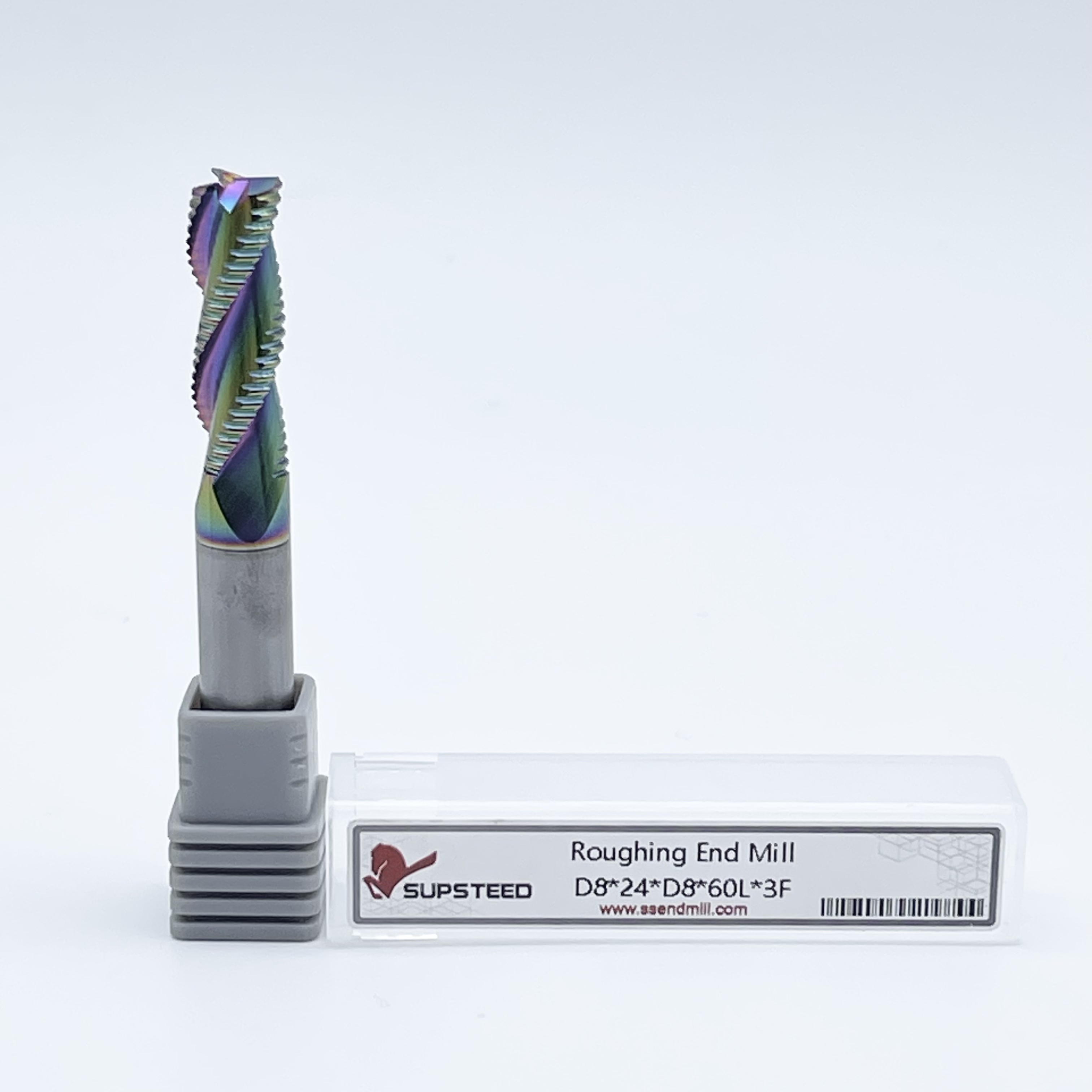
Toolpaths like OptiRough typically utilize standard, multi-flute solid carbide end mills rather than specialized geometries. The performance comes from the code, not just the carbide. The low radial engagement allows the tool to cool during the non-cutting portion of its rotation. Because the tool spends less time engaged in the material per revolution, heat dissipates into the chip rather than accumulating in the tool and workpiece. This thermal management proves highly effective when machining heat-resistant superalloys, stainless steel, or titanium.
Chip evacuation is another critical factor in this strategy. Because the tool takes such deep axial cuts, the flutes can quickly pack with chips if not properly cleared. Operators typically use high-pressure air blasts rather than flood coolant when running these toolpaths in steel. Flood coolant can cause thermal shock—rapid heating and cooling of the carbide—leading to micro-fractures along the cutting edge. An air blast clears the chips effectively while allowing the tool to maintain a stable operating temperature.
Both strategies leverage the principle of chip thinning to achieve massive material removal rates without catastrophic tool failure. They manipulate chip thickness through entirely different mechanisms. Understanding how each method controls chip load dictates how you program feeds and speeds at the controller.
Chip thinning in this context is entirely geometry-driven. When a tool has a shallow lead angle, the physical chip created during the cut is significantly thinner than the actual advance per tooth (IPT) programmed into the machine. Consider a standard 90-degree shoulder mill. If you program a feed rate of 0.010 inches per tooth, the physical chip thickness is exactly 0.010 inches. However, with a 10-degree lead angle on a high feed cutter, that same 0.010-inch programmed feed rate might only produce a chip that is 0.002 inches thick.
To get the chip back to the required 0.010-inch thickness to properly shear the metal, you must increase the programmed feed rate by a factor of five. This mathematical relationship is the core secret behind the massive table feeds achieved by these tools. If you program a standard feed rate, the resulting chip will be so thin that the cutting edge will rub against the material rather than shearing it. This rubbing generates excessive heat, destroys the cutting edge, and causes rapid work hardening of the workpiece.
This geometry also enables highly effective constant profile ramping. This specific technique leverages axial chip thinning to enter materials faster and more efficiently than traditional plunging or helical interpolation. The tool can ramp down into solid material at aggressive angles, clearing out pockets rapidly without the need for pre-drilled starter holes.
Here, chip thinning is toolpath-driven rather than geometry-driven. When the radial depth of cut (RDOC) drops below 50% of the tool diameter, the maximum chip thickness decreases. In these advanced CAM strategies, the RDOC is typically kept under 15% of the tool diameter. Because the cutter takes such a thin radial slice, the chip never reaches the full programmed advance per tooth.
The physics of heat transfer play a massive role here. In traditional roughing, the tool spends a significant portion of its rotation buried in the material, absorbing heat. With a low radial depth of cut, the cutting edge is only engaged in the material for a brief fraction of a second. As the flute exits the cut, the heat transfers directly into the chip. When the chip flies away from the cutting zone, it takes the heat with it. This leaves both the workpiece and the solid carbide end mill surprisingly cool, even during aggressive material removal.
Just as with the axial method, programmers must increase the feed rate to achieve the proper chip thickness. The critical component here is the constant engagement factor. In traditional offset toolpaths, a tool might take a 15% radial cut on a straight line, but suddenly engage 100% of the tool diameter when plunging into a 90-degree corner. This sudden spike in tool load causes instant breakage.
Advanced CAM software solves this by dynamically adjusting the feed rate and toolpath motion in corners. The software generates trochoidal or peeling motions, ensuring the tool never exceeds its programmed engagement angle. This maintains a consistent chip load, prevents tool breakage, and allows standard solid carbide tools to survive incredibly aggressive cutting parameters.
Selecting the correct approach requires mapping the technical mechanics to specific machining scenarios, workpiece constraints, and material types. A strategy that excels in heavy steel roughing may completely destroy a delicate aluminum component.
Application Suitability Matrix
| Machining Scenario | High Feed Strategy | High Efficiency Strategy |
|---|---|---|
| Deep Cavity Pocketing | Excellent (Axial forces prevent chatter) | Poor (Long flute engagement causes harmonics) |
| Thin-Walled Components | Poor (Axial pressure crushes unsupported floors) | Excellent (Low radial force prevents wall deflection) |
| Hardened Steels & Cast Iron | Excellent (High rigidity, robust inserts) | Moderate (Requires highly specialized carbide) |
| Thermally Sensitive Alloys | Moderate (Generates significant heat in cut) | Excellent (Excellent heat dissipation into chips) |
When machining deep cavities, tool overhang becomes a primary constraint. Machinists evaluate tool overhang using the Length-to-Diameter (L/D) ratio. Standard end mills begin to struggle and induce chatter at a 3xD overhang. High feed cutters, due to their axial force vectoring, can comfortably rough out pockets at 5xD, 7xD, or even 10xD overhangs. The downward pressure stabilizes the extended tool holder, making it the only viable option for deep mold cavities or complex forging dies.
This makes the axial strategy the preferred choice for aggressive roughing in steel, cast iron, and hardened alloys. In these tough materials, tool rigidity is paramount. The robust design of these cutters can withstand heavy impact loads that would chip the delicate flutes of a standard end mill.
Conversely, utilizing a CAM-driven constant engagement strategy in deep pockets with long tool holders often leads to failure. Because this method relies on utilizing the full flute length (high ADOC), a long tool will experience severe radial pressure along its entire extended length. This massive radial contact area inevitably leads to harmonic vibration issues, causing the tool to scream, chatter, and eventually fail.
The rules change entirely when machining fragile parts, such as thin-walled aerospace wing ribs or delicate medical components. In these scenarios, the low radial cutting forces of a constant engagement toolpath are ideal. Because the tool is only taking a tiny radial bite (often 5-10% of the diameter), there is very little pressure pushing against the side of the workpiece. This prevents thin walls from distorting or bending away from the cutter during the roughing pass.
Applying an axial-heavy strategy to delicate parts introduces severe risks. The massive downward pressure generated by the shallow lead angle can push down on unsupported part features. If you are machining a thin floor, the axial force will cause the floor to bow downward. Once the tool passes, the floor springs back up, leaving an uneven surface and out-of-tolerance dimensions. Furthermore, this heavy downward thrust can easily overcome weak workholding, pushing the part right out of the vise or fixture.
Beyond the physics of cutting metal, shop managers must analyze the scalability, cost-per-part, and impact on machine downtime when selecting between these strategies. The physical tooling required for each method dictates how operators interact with the machine during production runs.
For roughing massive volumes of material, indexable tooling offers a distinct economic advantage. Large-diameter indexable cutters are highly cost-effective because they significantly reduce the need for complete tool changeouts. When a cutting edge wears out, the operator simply unscrews the insert, rotates it to a fresh edge, and tightens it back down.
This process drastically reduces machinist intervention and machine downtime. Every minute the spindle is not turning, the shop loses money. Because the tool body remains in the spindle or tool holder, the operator does not need to perform a full tool touch-off to establish new length offsets. The Z-height remains consistent across insert rotations. This lessens production errors associated with manually entering tool offsets into the controller.
The return on investment becomes obvious when comparing insert replacement versus solid tool regrinding. Shipping solid carbide tools out for regrinding and recoating involves logistical overhead and requires keeping a large float of backup tools in inventory. Indexable tools, particularly when utilizing constant profile ramping to clear pockets, provide a robust, predictable roughing cycle that keeps the spindle turning with minimal interruption.
While indexable tools dominate the axial strategy, the CAM-driven constant engagement strategy relies almost exclusively on solid carbide end mills. This necessity stems from the mechanics of the cut. To maintain a high feed rate with a low radial engagement, the tool needs multiple flutes (often 5, 7, or 9 flutes) to keep the chip load manageable.
To understand why standard end mills fail and specialized solid carbide succeeds in this strategy, look at the flute geometry. High-performance end mills feature variable pitch and variable helix designs. In a standard end mill, the flutes are spaced evenly, meaning they strike the material at the exact same frequency, which creates harmonic chatter. Variable pitch alters the spacing between the flutes, breaking up the rhythmic impact and eliminating the harmonic vibration. This allows the tool to run smoothly even when buried two inches deep in a block of titanium.
High concentricity is also mandatory. If a tool has even a thousandth of an inch of runout, a low-radial cut will result in only one or two flutes doing all the work, leading to rapid failure. Solid carbide provides the necessary precision. Because the CAM software perfectly dials in the cutting parameters and prevents sudden load spikes, these end mills can last for hours in the cut. This extended tool life effectively offsets their initial cost, making the strategy highly economical for shops equipped with the right software.
Adopting high-performance roughing techniques introduces new variables to the shop floor. Identifying where shops typically fail during implementation protects expensive machine tools and prevents scrapped parts.
The primary risk when implementing advanced CAM-driven roughing is data starvation at the CNC controller. These toolpaths generate massive amounts of G-code due to the complex, sweeping trochoidal motions. If the CNC controller lacks sufficient block processing speed (often called look-ahead capability), it cannot read the code fast enough to keep up with the programmed feed rate.
To check if your machine is suffering from data starvation, listen to the cut. A properly executing dynamic toolpath should sound like a smooth, continuous hum. If the machine sounds like it is accelerating and decelerating rapidly, or if you hear a rhythmic knocking sound in the corners, the controller is bottlenecking the code. You may need to adjust the smoothing tolerance in your CAM software to output fewer, longer lines of G-code, reducing the processing burden on the CNC controller.
Conversely, the primary risk with axial-heavy roughing involves the physical hardware of the machine. Older or lighter-duty machines may not withstand the continuous axial pounding generated by these specialized cutters. The constant downward force accelerates wear on the Z-axis thrust bearings and ball screws. Over time, this degrades the machine's overall Z-axis accuracy.
Mitigating the risks of constant engagement roughing requires upgrading to modern CAM packages. You cannot program these toolpaths by hand at the control, and standard offset toolpaths cannot be used. The software must be capable of generating dynamic, trochoidal motions that actively monitor and adjust the tool's engagement angle. Attempting to run a high ADOC / low RDOC strategy with standard pocketing code will result in immediate tool breakage in the corners.
Mitigating risks for the axial strategy requires precise tool definition within the CAM environment. Programmers must ensure the CAM software can accurately simulate the specific non-standard profile of the cutter. If the software assumes the tool is a standard flat bottom end mill, it will miscalculate the remaining stock. This leads to gouging the part or leaving excessive rest material in corners, which will subsequently break the finishing tool on the next operation.
A: No. High feed cutters are designed with a shallow lead angle for low axial depth of cut and high feed rates. High efficiency milling requires tools capable of deep axial cuts and low radial cuts. Using a high feed geometry for a constant engagement toolpath will cause immediate tool failure.
A: HSM traditionally focuses on elevated spindle speeds and lighter feed rates to achieve excellent surface finishes. HEM is a specific CAM-driven roughing strategy that maintains a constant radial tool engagement angle, allowing for deep axial cuts and aggressive material removal rates without overloading the tool.
A: Choose an indexable tool for heavy roughing in steel, long-reach applications, and high-volume production where minimizing machine downtime is critical. Indexable tools allow operators to quickly rotate inserts rather than performing complete tool changes and resetting length offsets.
A: Yes. You cannot program this strategy manually or use standard offset pocketing routines. It requires modern CAM software capable of generating dynamic, trochoidal toolpaths that continuously calculate and adjust the tool's engagement angle to prevent load spikes in corners.
A: The specialized multi-radii geometry of the cutter creates a shallow lead angle. This physical shape causes the actual chip thickness to be much smaller than the programmed advance per tooth. Programmers must drastically increase the feed rate to achieve the correct chip load and prevent rubbing.
A: Stuttering is caused by data starvation. Complex dynamic toolpaths generate massive amounts of G-code. If your CNC controller lacks sufficient block processing speed, it cannot read the code fast enough to maintain the programmed feed rate, causing the machine to jerk and pause.