- All
- Product Name
- Product Keyword
- Product Model
- Product Summary
- Product Description
- Multi Field Search

Views: 0 Author: Site Editor Publish Time: 2026-08-19 Origin: Site

High-speed CNC machining of soft, gummy, or heat-sensitive materials frequently fails at the intersection of chip clearing and thermal management. When chips pack into a slot, you get broken tools and scrapped parts. Machinists and production engineers must balance aggressive Material Removal Rates (MRR) with acceptable surface finishes. Poor tool selection directly causes chip recutting, chip welding on the cutting edge, and excessive post-processing to fix surface defects.
Understanding the exact mechanical trade-offs of single flute upcut end mills—specifically how their geometry dictates chip extraction and shear dynamics—is necessary for optimizing cycle times. You need to know exactly how these tools behave under heavy radial loads to determine if they are the correct tooling choice for your specific material and workholding setup.
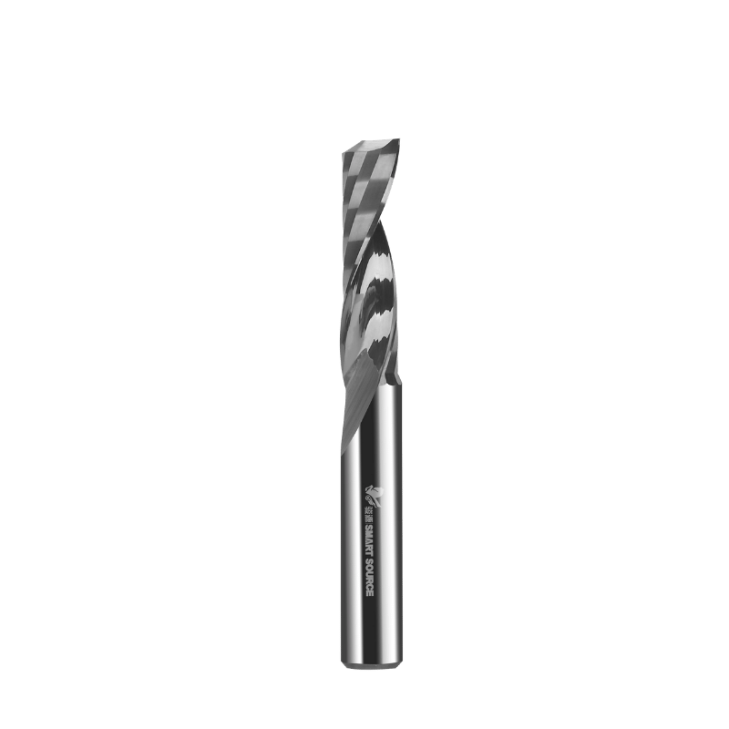
The defining characteristic of an upcut tool is its right-hand spiral combined with a right-hand cut direction. As the machine spindle rotates clockwise (standard M03 command), the helical flute wraps upward around the tool body. This specific shear angle dictates how the carbide cutting edge engages the raw stock. Instead of striking the material squarely like a straight flute, the edge slices into the stock from the bottom up. This shearing action reduces the sudden impact load on the spindle bearings and creates a smoother, more continuous cutting dynamic.
Physics dictate that this bottom-up engagement generates a distinct upward lifting force. The cutting forces direct toward the spindle, physically pulling the material away from the machine bed. Simultaneously, the helical geometry acts as a mechanical auger. As the tool rotates at high RPMs, the spiral channel physically pulls chips vertically out of the cutting zone. This continuous extraction prevents waste material from remaining in the tool path, which is the primary cause of tool breakage in deep slotting operations.
The helix angle itself plays a massive role in this dynamic. A high helix angle (closer to 45 degrees) pulls chips out faster and leaves a smoother finish, but it creates a sharper, more fragile cutting edge. A lower helix angle (around 20 to 30 degrees) provides a stronger cutting edge that resists chipping, though it sacrifices some vertical extraction speed. You must match the helix angle to the hardness of the material you are cutting.
Tool geometry always involves a strict compromise between core strength and chip clearance. A single flute end mill features a much thinner cross-sectional core compared to 2-flute, 3-flute, or 4-flute alternatives. Removing the secondary and tertiary flutes opens up the tool body entirely. This design choice maximizes the size of the chip gullet—the open valley where chips form, curl, and flow out of the cut.
The relationship between flute count and gullet size is inverse. Fewer flutes mean larger gullets. When machining materials that produce stringy, bulky, or sticky chips, a large gullet prevents the channel from choking. However, relying on a single cutting edge completely alters your machining parameters. To maintain a specific chipload (feed per tooth), you must adjust your spindle RPM and feed rate drastically.
A multi-flute tool hits the material multiple times per revolution. A single flute tool only strikes once. You must either increase your feed rate or decrease your spindle speed to ensure the single edge takes a thick enough bite of material. If you run a single flute tool at the same feeds and speeds as a 3-flute tool, you will reduce your chipload by 66%. The tool will stop cutting and start rubbing, generating massive amounts of friction and heat.
To properly set up a single flute tool, follow these parameter adjustments:
The absence of secondary flutes creates maximum volumetric space for chip formation. When you push a CNC machine for high Material Removal Rates (MRR), the volume of waste generated per second increases drastically. If the tool cannot evacuate this waste faster than it generates it, the chips compress. This leads to chip packing, where waste material fuses into a solid, immovable mass inside the cut channel.
This open volumetric space becomes critical during high-speed roughing passes. Bulk material removal is the primary success criterion here. You want to clear out large pockets or deep slots quickly without babysitting the machine. upcut end mills with a single flute excel in these operations because the massive gullet accommodates thick, heavy chips without clogging. The tool can plow through the material aggressively without the fear of stalling the spindle or snapping the carbide.
In practical shop floor applications, this means you can increase your Depth of Cut (DOC) significantly. Instead of taking multiple shallow passes to prevent chip buildup, a single flute tool allows you to step down deeper into the material, utilizing more of the flute length and reducing the overall cycle time.
Thermodynamics dictate the success or failure of chip formation. When a carbide cutting edge shears material, it generates intense friction and heat. Ideally, this heat transfers directly into the chip itself. The chip then carries the thermal energy away from the cut zone as it ejects. Thicker chips possess more mass, allowing them to absorb and carry away significantly more heat than thin, powdery chips.
Single flute tools inherently take thicker chips per revolution when programmed correctly. This mechanism prevents heat accumulation in the cut zone. In non-ferrous metals like 6061-T6 aluminum, excess heat causes the material to soften and weld directly to the cutting edge—a condition known as Built-Up Edge (BUE). Once BUE forms, the tool stops cutting and acts like a blunt hammer, destroying the part and eventually snapping.
In thermoplastics, excess heat causes the material to melt and wrap around the tool body. By ejecting thick, hot chips rapidly, single flute tools drastically reduce the risk of BUE and melting. Furthermore, rapid vertical extraction eliminates chip recutting. Recutting happens when a tool chops up chips already severed from the stock. This doubles the heat generation, destroys the surface finish, and accelerates premature tool wear.
The physical orientation of the upcut spiral dictates the exact trajectory of the ejected chips. The right-hand helix physically lifts chips out of deep pockets and blind slots. Gravity and cutting forces naturally work against chip extraction in deep cavities. The auger effect of the upcut geometry overcomes these forces, throwing the chips clear of the work area.
Contrast this behavior with downcut or straight flute geometries. Downcut tools push chips downward, packing them tightly into the bottom of the cut. Straight flutes merely push chips around horizontally, relying entirely on air blasts or coolant to clear the channel. In deep slotting operations, trapping chips at the bottom of the cut guarantees failure. The tool will recut the packed chips, generate massive friction, and eventually snap under the torsional load. The vertical extraction of the upcut design is non-negotiable for deep pocketing.
The cutting action on the workpiece surfaces varies dramatically depending on the tool's shear direction. The upcut shearing motion pulls material upward. At the bottom of the cut, the material is fully supported by the stock beneath it or the spoilboard. This results in a pristine, clean bottom edge finish. The cutting edge slices cleanly through the supported fibers or grain structure without tearing.
However, this creates an inherent risk to the top edge. As the cutting edge exits the top of the material, there is no supporting structure above it. The upward lifting forces can cause fraying, burring, or tear-out. The severity depends entirely on the material's tensile strength and grain structure. Hard plastics might show slight burring that requires deburring, while layered materials like plywood will experience severe splintering along the top veneer.
To mitigate top-edge tear-out while using an upcut tool, you can utilize a two-pass strategy. Leave a small radial allowance (e.g., 0.020 inches) on the roughing pass. Then, perform a full-depth finishing pass at a higher RPM and lower feed rate. The lighter radial load reduces the upward pulling force, resulting in a cleaner top edge.
Tool marks, often seen as scalloping or chatter marks on the sidewalls and floor, are direct results of machining mechanics. A single cutting edge rotating at high speeds leaves distinct witness marks if the feed rate is not perfectly calibrated. Because there is only one flute, the distance between each cut (the chipload) is physically wider than it would be with a multi-flute tool.
Bottom-of-cut tool marks present another challenge. Tool deflection or improper spindle tramming combined with a single cutting edge can leave distinct swirl marks on the floor of a pocket. If the spindle is not perfectly perpendicular to the machine bed, the single flute will dig in slightly deeper on one side of its rotation. You must calibrate feed rates precisely. Running too fast leaves widely spaced, visible scallops on the sidewalls. Running too slow causes the tool to rub, generating heat and smearing the surface finish.
Climb milling versus conventional milling also impacts tool marks. Climb milling (where the tool rotates into the direction of feed) throws the chip behind the cutter. This prevents the single flute from recutting the chip on its next rotation, generally yielding a superior sidewall finish compared to conventional milling.
Machinists face a strategic dilemma: use the same bit for an entire operation or implement tool changes. Single flute tools are highly viable for aggressive roughing passes. During roughing, MRR and chip evacuation are prioritized over surface finish. You want to hog out material as fast as the machine allows without breaking the tool or stalling the spindle.
Relying on a single flute for the final finishing pass often yields subpar sidewall smoothness. You should transition to a multi-flute tool for the final finishing pass. Multi-flute tools take smaller, more frequent bites, reducing the physical size of the scallops left on the sidewall. Use the single flute to clear the bulk of the pocket, leaving a small radial allowance. Then, swap to a 3-flute or 4-flute end mill to clean up the walls and achieve superior smoothness.
Single flute end mills suffer from a structural weakness: a thinner core means lower overall tool rigidity. Carbide is stiff but brittle. When you apply heavy radial loads (cutting sideways through material), the tool bends slightly. This bending is called deflection. The longer the tool stick-out from the collet, the exponentially worse the deflection becomes.
Tool deflection compromises dimensional accuracy. If the tool bends away from the cut, the resulting pocket will be undersized, or the walls will be tapered. Deflection also degrades surface finish, inducing chatter and vibration that transfers directly into the workpiece. To minimize deflection, you must balance Depth of Cut (DOC) and Width of Cut (WOC). Reduce your radial engagement (WOC) when taking deep axial cuts (DOC). Never push a single flute tool to 100% radial engagement at a depth greater than its own diameter unless you are cutting very soft materials like foam.
Troubleshooting Tool Deflection in Single Flute Applications
| Symptom | Root Cause | Corrective Action |
|---|---|---|
| Tapered Sidewalls (Pocket narrower at bottom) | Tool bending away from the cut under heavy radial load. | Reduce Width of Cut (WOC) or add a spring pass (zero-stock finishing pass). |
| Heavy Chatter Marks on Walls | Excessive tool stick-out causing harmonic vibration. | Seat the tool deeper into the collet. Use the shortest flute length possible. |
| Screaming or High-Pitched Noise | RPM too high for the current feed rate, causing rubbing and vibration. | Increase feed rate to thicken the chip, or decrease spindle RPM. |
| Tool Snapping at the Shank | Feed rate exceeds the shear strength of the thin carbide core. | Reduce feed rate or decrease Depth of Cut (DOC) to lower cutting forces. |
Single flute upcut tools, often branded as O-flutes, dominate plastic and acrylic machining. Materials like cast acrylic, polycarbonate, and High-Density Polyethylene (HDPE) are highly sensitive to heat. If the tool rubs or takes chips that are too thin, the plastic melts instantly, ruining the part and destroying the tool.
The O-flute geometry features a highly polished, open gullet that curls the plastic chip efficiently. This prevents localized melting. When run at the correct chipload, a single flute tool produces a polished edge straight off the machine, eliminating the need for manual flame polishing or edge scraping. The upcut action pulls the plastic chips out of deep channels, preventing them from re-welding behind the tool path.
Extruded acrylic requires even stricter parameter control than cast acrylic. Extruded acrylic has a lower melting point and tends to gum up faster. You must maintain a high feed rate and utilize compressed air blasts to clear chips and cool the cutting zone simultaneously.
Machining gummy aluminum alloys like 6061-T0 or 5052 presents massive chip evacuation challenges. These materials stick to carbide easily. Single flute tools are highly effective in these alloys for preventing chip packing during roughing operations. The large gullet clears the sticky aluminum chips before they can fuse to the tool body.
However, 3-flute end mills dominate aluminum finishing. A 3-flute tool distributes cutting forces across multiple edges, reducing per-edge wear. It offers a thicker, more rigid core that resists deflection during high-speed finishing passes. Use a single flute to rough out the aluminum pocket rapidly, then switch to a 3-flute tool equipped with a corner radius to finish the floor and walls to a mirror shine. Always use Minimum Quantity Lubrication (MQL) or flood coolant when cutting aluminum to prevent chip welding.
Wood machining requires careful consideration of grain direction and material layers. In plywood, MDF, and natural woods, the upward pulling force of an upcut tool creates a high risk of top-edge tear-out. The tool will lift and splinter the top veneer of the plywood, requiring extensive sanding or scrapping the part entirely.
Specify upcut end mills only when bottom-edge finish is critical or when cutting through-pockets where waste removal is the primary concern. If you need clean edges on both the top and bottom of a sheet of plywood, a compression bit (which combines upcut and downcut geometries) is the superior choice. Reserve single flute upcut tools for deep mortising or roughing out large pockets in solid hardwoods where chip clearing dictates the success of the operation.
The primary implementation risk of using upcut geometries is the upward pulling force lifting the workpiece off the CNC bed. If the material shifts during the cut, the tool will break, and the part will be ruined. Thin sheet stock is particularly vulnerable to this lifting action. A 1/8-inch aluminum sheet will bow upward in the center if not properly secured.
You must implement strict mitigation strategies. High-vacuum hold-down systems are mandatory for nesting operations on CNC routers. Ensure your vacuum zones are properly gasketed to prevent leaks. If vacuum hold-down is unavailable, use robust mechanical clamping around the entire perimeter of the stock. For small or thin parts, double-sided tape or the painters-tape-and-cyanoacrylate (superglue) method provides excellent resistance against upward lifting forces. Never attempt heavy upcut roughing on poorly secured sheet goods.
Calculating optimal feeds and speeds for single flute tools requires a strict framework. You must maintain the target chipload without inducing chatter. The formula is straightforward: Feed Rate = Spindle RPM × Number of Flutes × Target Chipload. Because the number of flutes is one, your feed rate must match the RPM and chipload directly.
Running the tool too slow poses a massive risk. If the feed rate drops, the tool stops cutting and starts rubbing. Rubbing generates extreme heat, leading to melted plastics or welded aluminum. Conversely, running too fast exceeds the shear strength of the thin carbide core, resulting in immediate tool breakage. Start at the manufacturer's recommended chipload, listen to the cut, and increase the feed rate until the chips are thick and well-formed without causing the spindle to bog down.
Wear dynamics on a single flute tool are highly concentrated. A single cutting edge takes 100% of the wear. This potentially reduces overall tool life compared to multi-flute tools that distribute the load across two, three, or four edges. You will replace single flute tools more frequently in high-volume production environments.
Address tool fragility and repairability before scaling production. Single flute geometries are highly susceptible to edge chipping if dropped or crashed into hard fixtures. Furthermore, their complex, deep-fluted geometry makes them difficult or impossible to regrind compared to standard multi-flute tools. You must weigh cost-to-performance trade-offs. In gummy materials, the operational efficiency gained by eliminating scrapped parts from chip packing heavily outweighs the cost of faster tool replacement.
A: No. Single flute tools lack the core rigidity required to shear hard metals like steel or titanium. The thin carbide core will deflect severely and snap under the high cutting forces. Use multi-flute tools with thicker cores for ferrous metals.
A: The upcut geometry pulls the wood fibers upward as it exits the cut. Because there is no material supporting the top veneer, it splinters and tears out. Switch to a downcut or compression bit for clean top edges on laminated woods.
A: Melting occurs due to friction from rubbing. You must increase your feed rate or lower your spindle RPM to ensure the cutting edge takes a thicker bite. Thicker chips carry the heat away from the cut zone before the plastic can melt.
A: Yes, they produce a louder, more distinct cutting noise. Because there is only one cutting edge engaging the material per revolution, the interrupted cutting action creates a lower frequency vibration and louder acoustic profile during heavy cuts.
A: While many single flute tools are center-cutting and can plunge, it is not recommended for deep holes. Plunging straight down traps chips under the tool. Always use a ramping or helical toolpath to allow chips to evacuate while entering the material.
A: Signs of excessive deflection include tapered sidewalls, heavy chatter marks, and a loud screaming noise during the cut. Reduce your depth of cut or width of cut to minimize radial pressure on the tool core.