- All
- Product Name
- Product Keyword
- Product Model
- Product Summary
- Product Description
- Multi Field Search

Views: 0 Author: Site Editor Publish Time: 2026-08-11 Origin: Site

In precision machining, relying on guesswork or generic estimates for cutting parameters directly results in premature tool failure, poor surface finish, and scrapped parts. Machinists and manufacturing engineers must balance aggressive Material Removal Rates (MRR) to reduce cycle times against the high cost of replacing broken or worn carbide tooling. You cannot simply load a tool, guess a spindle speed, and hit cycle start. Establishing a reliable baseline requires understanding the exact mathematical formulas, the physical variables of the workpiece, and the implementation realities of your specific CNC machine setup. Every material behaves differently under the cutter, and your parameters must reflect the specific geometry of the tool, the rigidity of your workholding, and the thermal limits of the carbide grade you are using.
To evaluate tooling efficiency and program toolpaths, operators must first calculate the theoretical baseline parameters before adjusting for real-world conditions. You cannot optimize a cutting process without first establishing a mathematical foundation. These formulas translate the physical properties of the cutting tool and the workpiece into actionable machine commands. Skipping this step and relying on the override dial on your CNC control is a guaranteed way to burn up end mills.
Spindle speed determines how fast the cutting tool rotates in the spindle. We define the standard inch formula as RPM = (SFM × 3.82) / Tool Diameter. This calculation tells the CNC machine exactly how many revolutions per minute the spindle must turn to achieve the desired surface speed for a specific material.
Understanding the mathematical derivation helps build foundational knowledge on the shop floor. The 3.82 constant simplifies the equation used to convert surface feet to rotational circumference. Originally, the formula uses 12 inches divided by Pi (π). Since 12 divided by 3.14159 equals approximately 3.82, we use this constant to streamline manual math at the machine control.
For shops utilizing the metric system, the formula changes to accommodate different units of measurement. The metric equivalent is RPM = (Vc × 1000) / (π × Tool Diameter). In this version, Vc represents cutting speed in meters per minute, and the tool diameter is measured in millimeters. The result is exactly the same physical rotational speed, just calculated using metric inputs.
You will often need to perform a reverse calculation for troubleshooting purposes. If you know the RPM from an old program but need to find the actual SFM to see if it matches current tooling capabilities, use this formula: SFM = (RPM × Tool Diameter) / 3.82. This reverse math helps operators verify if a pre-programmed toolpath is running too hot or too cold for a specific material block.
RPM dictates the heat generated at the cutting edge. Running at the proper RPM is the most critical aspect of milling. If the RPM is too high, the tool will overheat, breaking down the carbide binder and causing rapid edge failure. If the RPM is too low, the tool may chip or break due to excessive mechanical pressure and built-up edge (BUE).
Feed rate determines how fast the machine drives the tool through the workpiece. We define the standard formula as Feed Rate (IPM) = RPM × Chip Load per Tooth (IPT) × Number of Flutes. This calculation ensures each cutting edge takes a consistent, measurable bite of material during every rotation.
We often introduce Feed per Revolution (IPR) as an intermediate metric when dialing in a process. You calculate it as IPR = Chip Load × Number of Flutes. IPR tells you exactly how far the tool advances during one complete 360-degree rotation, which is highly useful when programming drilling or plunging operations with an end mill.
Let us look at a concrete calculation example. Imagine a 4-flute end mill running at 2,000 RPM with a 0.006" chip load. The carbide end mill feed rate is 48 IPM. You find this by multiplying 2,000 by 4, and then multiplying that result by 0.006. If you switch to a 5-flute tool at the same RPM and chip load, your feed rate jumps to 60 IPM.
To calculate your feed rate manually at the machine, follow these steps:
Feed rate controls the mechanical load on the tool and the thickness of the chip. A proper feed rate ensures the chip carries heat away from the cutting zone. If the feed rate drops too low, the tool rubs against the material instead of shearing it, causing work hardening and catastrophic tool failure.
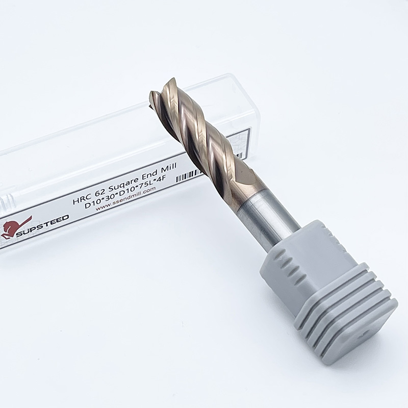
Assessing how specific tool geometries and workpiece materials alter baseline calculations is essential for successful machining. You must properly configure speeds and feeds for carbide end mills to maximize efficiency and prevent tool breakage. A baseline formula only gets you halfway there; understanding the physical variables takes you the rest of the way.
We define SFM as the speed at which the cutting edge moves through the material. It represents the linear velocity of the tool's outside diameter. SFM dictates the thermal limits of the cutting operation. If you exceed the SFM limit, you melt the tool. If you run too far below it, you waste valuable machine time.
The concept of material pairs is critical here. SFM is not just about the workpiece material alone. It describes how the specific cutting tool material interacts with the workpiece material. Carbide can run at much higher SFM than high-speed steel (HSS) because it withstands higher temperatures without losing its hardness.
Comparing SFM ranges for common materials highlights these differences. You typically machine 6061 aluminum at an aggressive 800 to 1500 SFM. In contrast, tough alloys like Ti-6Al-4V titanium require a highly conservative 100 to 250 SFM to prevent rapid tool wear and thermal cracking.
Material hardness and thermal conductivity dictate the maximum allowable SFM for carbide. Harder materials generate more friction, requiring lower spindle speeds. Materials with low thermal conductivity, like 304 stainless steel, trap heat at the cutting edge instead of dissipating it into the chip, meaning you must strictly control your SFM to survive the cut.
Common Material SFM Guidelines
| Workpiece Material | Typical SFM Range (Carbide) | Coolant Strategy | Recommended Flute Count |
|---|---|---|---|
| 6061 / 7075 Aluminum | 800 - 1500 | High-Pressure Flood | 2 to 3 Flutes |
| 1018 / A36 Low Carbon Steel | 300 - 500 | Flood or Mist | 4 to 5 Flutes |
| 4140 / 4340 Alloy Steel | 250 - 400 | Air Blast or Mist | 4 to 6 Flutes |
| 304 / 316 Stainless Steel | 150 - 300 | High-Pressure Flood | 4 to 6 Flutes |
| Ti-6Al-4V Titanium | 100 - 250 | High-Pressure Flood | 4 to 6 Flutes |
We define chip load as the exact amount of material removed by a single cutting edge in one revolution. It is a physical measurement of chip thickness. Maintaining the correct chip load is vital for tool longevity. A thick chip pulls heat away from the tool, while a thin chip leaves heat in the cutter.
You must analyze the trade-offs of flute count when selecting a tool for a specific job. Use 2 or 3 flutes for optimal chip evacuation in gummy materials like aluminum. Choose 4, 5, or even 7 flutes for increased core rigidity and higher feed rates in harder materials like steel and titanium.
Insufficient chip load causes rubbing and work hardening. When the tool rubs, it generates massive amounts of heat without removing material, dulling the edge instantly. Excessive chip load causes tool breakage because the mechanical cutting forces exceed the carbide's transverse rupture strength, snapping the end mill at the shank.
Tool diameter directly impacts rigidity and the allowable baseline RPM. Larger diameter tools possess greater core strength and withstand higher cutting forces, allowing for heavier chip loads. However, they require lower RPMs to maintain the same target SFM compared to micro-tooling.
You must understand the concept of radial chip thinning. When your radial depth of cut (stepover) is less than 50% of the tool diameter, the actual chip thickness decreases geometrically. This requires an increased programmed feed rate to maintain the target chip thickness and prevent rubbing. If you program a 10% stepover without adjusting your feed rate for chip thinning, your tool will fail prematurely.
The economic trade-offs between pushing a tool to its limits and maximizing its lifespan govern shop profitability. You must find the optimal balance point where material removal outpaces tooling costs. Running a machine too conservatively is just as detrimental to the bottom line as breaking tools every ten minutes.
We provide the MRR formula using standard shop terminology: MRR = Axial Depth of Cut (DOC) × Radial Depth of Cut (WOC) × Feed Rate (IPM). This calculation measures exactly how many cubic inches of material the machine removes per minute. It is the ultimate metric for roughing efficiency.
Optimizing speeds and feeds for higher MRR reduces cycle times and increases machine profitability. A machine sitting idle or cutting too slowly costs money. Pushing the MRR safely ensures you maximize spindle utilization. For example, taking a deeper axial cut with a lighter radial stepover often yields a higher MRR than traditional shallow pocketing.
Carbide grades and advanced coatings allow for higher SFM by resisting thermal breakdown. Coatings like Titanium Aluminum Nitride (TiAlN) and Aluminum Titanium Nitride (AlTiN) oxidize at high temperatures to form a protective ceramic layer. This layer shields the raw carbide substrate from the intense heat of the cutting zone.
You must evaluate the economic threshold of your machining process. There is a point when the cost of faster tool wear outweighs the cost savings of reduced cycle times. Replacing a broken end mill every hour is rarely profitable, even if the cycle time is exceptionally fast. You want a predictable process where a tool lasts for a known number of parts before requiring a scheduled change.
Theoretical calculations often fail in practice due to environmental and mechanical constraints. A formula cannot account for a loose vise, a worn spindle bearing, or a flimsy fixture. You must adjust your parameters based on the physical realities of the machine in front of you.
Lack of machine mass or workholding rigidity introduces vibration. Vibration destroys carbide rapidly. If your setup lacks rigidity, you must implement a reduction in calculated feed rates and depths of cut. A 40-taper machine cannot take the same cut as a 50-taper machine, regardless of what the math says.
You must verify if the calculated MRR exceeds the spindle's available horsepower or torque curve. Pushing a machine beyond its horsepower limit causes the spindle to stall mid-cut. This usually results in immediate tool breakage, scrapped parts, and potential damage to the spindle bearings.
Excessive tool stick-out increases deflection. When a tool deflects, it bends slightly during the cut. This alters the effective chip load, reduces dimensional accuracy on the workpiece, and causes premature failure at the cutting edge. Always hold the tool as short as possible in the collet or shrink-fit holder.
Spindle runout unevenly distributes chip load across the flutes. If one flute takes a heavier cut than the others due to runout, it will wear out faster or chip. High runout requires conservative feed adjustments to protect the tool. Check your toolholders and spindle taper regularly with a dial indicator.
You must outline mitigation strategies for chatter. Chatter is a self-exciting vibration that leaves poor surface finishes and destroys cutting edges. Use variable pitch and variable helix end mills to break up harmonics. If chatter occurs, adjust your RPM up or down by 10% to move out of the machine's resonant frequency.
Speeds and Feeds Troubleshooting Guide
| Observed Issue | Probable Cause | Corrective Action |
|---|---|---|
| Tool chipping at the cutting edge | Feed rate too high or excessive runout | Decrease IPM or check toolholder runout |
| Built-up edge (material welding to tool) | RPM too low or poor coolant application | Increase RPM or improve coolant flow |
| Rapid flank wear (tool dulling quickly) | RPM too high for the material | Decrease SFM / RPM |
| Loud squealing or chatter marks | Lack of rigidity or harmonic resonance | Adjust RPM by 10%, decrease stick-out |
| Tool snapping at the shank | Chip packing or excessive depth of cut | Clear chips with air/coolant, reduce DOC |
Evaluate when to use flood coolant versus air blast. You should use high-pressure flood coolant for optimal chip evacuation and lubrication in aluminum. Aluminum tends to weld to the cutting edge if not properly lubricated, destroying the tool instantly.
Conversely, use air blast when cutting steel or titanium with coated carbide. Flood coolant can cause thermal shock in these high-heat applications. Thermal shock creates micro-fractures in the carbide, leading to rapid edge failure. The coating needs heat to activate, and air blast clears the chips without quenching the tool.
Methods for standardizing parameter generation across a machine shop vary widely. Some shops rely on tribal knowledge and handwritten notes, while others implement strict software-driven protocols to ensure consistency across all shifts.
Manufacturer tooling charts offer distinct advantages. The baseline data is specifically tested for the exact carbide grade, coating, and geometry of the tool you purchased. This provides a highly accurate starting point for your calculations.
However, these charts have drawbacks. They often represent ideal conditions with perfect workholding and massive, rigid machine tools. You will likely require manual adjustment for specific toolpaths, especially when utilizing High-Efficiency Milling (HEM) techniques on lighter-duty CNC machines.
Standalone calculators offer quick verification of material pairs and RPM/IPM outputs. Tools like Machining Doctor or dedicated manufacturer apps allow operators to double-check their math before pressing cycle start. They are excellent for quick spot-checks on the floor.
Modern CAM software provides immense value for complex programming. Advanced CAM automatically calculates radial chip thinning and dynamically adjusts feed rates based on tool engagement angles in the corners. This software removes much of the manual guesswork and protects the tool during heavy, variable engagement cuts.
Calculating accurate parameters is a dynamic process of establishing a mathematical baseline and adjusting for machine-specific variables. You must adapt your numbers based on the rigidity of your setup, the condition of your spindle, and the specific material batch you are cutting.
A: A feed rate that is too low causes the cutting edge to rub against the material instead of shearing it. This rubbing generates excessive friction and heat. The heat leads to rapid tool wear, work hardening of the workpiece, and poor surface finishes. You must maintain a minimum chip thickness to carry heat away.
A: High-speed machining utilizes light radial depths of cut and high feed rates. Because the radial engagement is low, you must calculate for radial chip thinning and significantly increase your programmed feed rate to maintain the proper chip thickness. You also generally increase the SFM due to reduced heat buildup.
A: No, the number of flutes does not affect the RPM calculation. RPM is determined solely by the material's Surface Feet per Minute (SFM) and the tool's physical diameter. Flute count only affects the feed rate (IPM) calculation.
A: Multiply your calculated RPM by the recommended chip load per tooth, and then multiply that result by 4 (the number of flutes). For example, 2000 RPM × 0.005" chip load × 4 flutes equals a feed rate of 40 Inches Per Minute.
A: Carbide is significantly harder and more heat-resistant than High-Speed Steel (HSS). This allows carbide end mills to run at much higher Surface Feet per Minute (SFM) without losing their cutting edge, resulting in faster cycle times and higher material removal rates.
A: When your stepover is less than half the tool diameter, the physical chip becomes thinner than the programmed chip load. You must increase your programmed feed rate to compensate for this thinning and maintain proper cutting mechanics, otherwise the tool will rub and fail.