- All
- Product Name
- Product Keyword
- Product Model
- Product Summary
- Product Description
- Multi Field Search

Views: 0 Author: Site Editor Publish Time: 2026-08-11 Origin: Site
Incorrect tooling selection directly impacts operational efficiency on the shop floor. Running the wrong cutter leads to broken tools, scrapped workpieces, poor surface finishes, and excessive spindle wear. Machining different materials requires fundamentally different approaches to chip evacuation, heat management, and shear angles. Metals, plastics, composites, and wood all behave differently under a cutting edge. A one-size-fits-all approach to tooling guarantees suboptimal cycle times and increased failure rates.
You need a systematic framework for evaluating and selecting cnc router end mills. This process relies on understanding material properties, flute geometry, feature requirements, and machine capabilities. By matching the specific physics of the cut to the correct tool geometry, you eliminate guesswork. The following guide breaks down exactly how to match your cutting tools to your target materials for maximum efficiency and predictable tool life.
Maximizing Material Removal Rate (MRR) dictates shop profitability. MRR measures the volume of material removed per minute. You calculate it by multiplying the depth of cut, width of cut, and feed rate. Pushing MRR requires a tool that can handle heavy chip loads without deflecting. Surface finish requirements often oppose high MRR. Roughing passes prioritize volume removal, while finishing passes prioritize surface quality. Predictable tool life bridges the gap between these two goals. If a tool snaps mid-cycle, the MRR drops to zero.
Flute count directly controls chip evacuation. An inverse relationship exists between the number of flutes and the size of the chip gullet. The gullet is the empty valley between the cutting edges. Fewer flutes mean larger gullets. Larger gullets allow massive chips to escape the cutting zone rapidly. This physical space is mandatory for softer materials that expand when cut. Adding more flutes increases the core diameter of the tool. A thicker core provides greater rigidity and reduces deflection under heavy side loads. However, it shrinks the available space for chip evacuation. If chips cannot escape, they pack into the flutes. Chip packing generates extreme friction. The tool rapidly overheats, welds to the material, and snaps.
Calculating the optimal chip load prevents this failure. Chip load, or feed per tooth, equals the feed rate divided by the product of spindle RPM and flute count. You must maintain a chip thickness that carries heat away from the tool without exceeding the flute's physical capacity. A chip that is too thin causes the tool to rub rather than shear. Rubbing generates heat and dulls the carbide edge prematurely. A chip that is too thick overloads the flute and breaks the cutter.
The bottom profile of the cutter determines the shape of the machined feature. Selecting the wrong profile ruins the part geometry and induces unnecessary tool pressure.
The spiral direction of the flutes dictates how the tool forces the material and the chips. Controlling this directional force is a primary factor in part finish and workholding strategy.
Micro-grain solid carbide dominates modern production routing. Carbide offers extreme rigidity, high heat tolerance, and superior wear resistance. It withstands the high RPMs generated by router spindles without losing its cutting edge. The manufacturing process of solid carbide involves sintering tungsten and carbon under extreme pressure. This creates a dense matrix that resists thermal deformation.
High-Speed Steel (HSS) costs less and offers higher flexibility. This flexibility makes HSS less prone to snapping under heavy vibration on older, less rigid machines. However, HSS dulls rapidly at high surface speeds. The heat generated by a router spindle running at 18,000 RPM will destroy an HSS edge in minutes. Solid carbide remains the strict industry standard for reliable, high-volume production routing.
Different materials demand specific cutting strategies. You cannot cut aluminum with the same geometry used for plywood. Mapping specific end mill geometries to the physical properties of your workpiece eliminates catastrophic failures.
Aluminum presents a unique mechanical challenge. It has a low melting point and high ductility. During machining, aluminum tends to gall and weld directly to the cutting edge. This phenomenon is called Built-Up Edge (BUE). Once BUE occurs, the tool stops cutting and starts rubbing. The friction spikes, the aluminum melts further, and the tool breaks instantly. Different alloys behave differently. 6061-T6 aluminum is gummy and highly prone to BUE. 7075 aluminum is harder, chips more cleanly, and machines better, but requires more rigid workholding.
To solve BUE, specify 2-flute or 3-flute end mills. You need maximum chip clearance to evacuate the sticky material. Never exceed 3 flutes for aluminum on a high-speed router. Utilize high helix angles, typically between 35 and 45 degrees. A high helix provides efficient shearing action, pulling the soft metal up and out of the cutting zone rapidly. Always use an air blast or minimum quantity lubrication (MQL) system to clear chips and cool the cutting zone.
Plastics share a similar vulnerability to heat but lack the structural integrity of metal. Low melting points cause the material to fuse around the tool if the feed rate drops or the RPM climbs too high. Friction is the primary failure mode. Cast acrylic cuts cleanly and produces distinct chips. Extruded acrylic is gummy and melts almost instantly if the chip load is incorrect.
Single-flute, or O-flute, cutters provide the ultimate solution for plastics. O-flutes maximize chip size. A larger chip absorbs more heat, carrying it away from the cut before the plastic can melt. Highly polished flutes are mandatory. The mirror finish reduces friction and prevents the soft plastic chips from sticking and re-cutting. Maintain a high feed rate to ensure the tool stays engaged and cuts rather than rubs.
Wood introduces grain direction, varying density, and the risk of splintering. Grain tear-out ruins expensive hardwood panels. Plywood and melamine face extreme delamination risks on the outer veneer layers. MDF contains highly abrasive glues that dull carbide edges rapidly. Climb milling generally produces a better surface finish on solid wood, but conventional milling is safer for roughing passes.
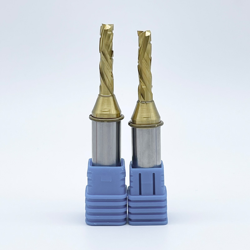
Compression bits are the standard for double-sided laminates and plywood. They shear inward from both faces, leaving perfectly clean edges. For standard pocketing where only the top-surface finish matters, use 2-flute down-cut bits. The downward shearing action slices the grain cleanly at the surface, eliminating fuzz and splinters. When machining deep pockets in solid wood, use an up-cut tool for the roughing passes to clear chips, followed by a down-cut tool for the final wall finish.
Composites consist of highly abrasive fibers suspended in tough resins. Machining carbon fiber, G10, or fiberglass destroys standard carbide edges rapidly. The abrasive nature acts like sandpaper against the cutting tool. Furthermore, improper geometry causes the layers to delaminate, ruining the structural integrity of the part.
Diamond-cut or chipbreaker router bits handle these tough materials. Specialized composite-cutting end mills feature high flute counts with serrated edges. These serrations sever the tough fibers cleanly without fraying the edges. They grind the material into a fine dust rather than pulling large chips, preventing delamination. Dust collection is mandatory when cutting composites, as the airborne particles are hazardous and highly abrasive to machine components.
Optimal Tool Configurations by Substrate
| Substrate Category | Primary Machining Challenge | Recommended Flute Count | Ideal Flute Geometry |
|---|---|---|---|
| Aluminum Alloys | Built-up edge (galling) | 2 to 3 | High Helix (35°-45°) Up-Cut |
| Cast & Extruded Plastics | Thermal deformation (melting) | 1 (O-Flute) | Polished Straight or Up-Cut |
| Hardwoods & Softwoods | Grain tear-out | 2 | Down-Cut |
| Laminated Plywood & MDF | Double-sided veneer chipping | 2 to 3 | Compression (Hybrid) |
| Carbon Fiber & G10 | Extreme abrasion and delamination | 10+ | Diamond-Cut / Chipbreaker |
Advanced tooling carries a premium cost. You must assess when that cost translates to measurable returns in a production environment. High-volume runs justify investments in specialized coatings and complex flute geometries.
Coatings alter the surface chemistry of the carbide. They increase surface hardness, reduce the coefficient of friction, and provide a thermal barrier between the tool and the workpiece. Uncoated carbide works well for general-purpose routing, but coatings multiply tool life in specific applications.
Standard end mills feature symmetrical flute spacing. At high speeds, this symmetry generates harmonic vibrations, commonly known as chatter. Chatter destroys surface finishes, sounds like a high-pitched squeal, and chips the cutting edge of CNC router bits.
Advanced geometries utilize variable helix angles and variable pitch spacing. By constantly changing the distance between cutting edges and the angle of the spiral, these tools disrupt harmonic frequencies. Variable helix end mills are an absolute necessity when pushing high material removal rates in aluminum or rigid materials. They stabilize the cut, eliminate chatter, and allow for significantly deeper passes.
Production efficiency requires separating bulk material removal from final dimensioning. Roughing end mills feature corncob or chipbreaker designs. The serrated edges break chips into tiny pieces, reducing spindle load and evacuating material rapidly. They leave a rough surface but clear massive volumes of material quickly without overloading the spindle.
Finishing end mills feature smooth, continuous cutting edges. They are designed for low-stepover, high-tolerance final passes. Using a rougher to clear the bulk and a finisher to hit the final dimension extends the life of your precise finishing tools and reduces overall cycle times. Never use a finishing tool for heavy slotting operations.
Even perfectly selected tools fail if the operational realities of the machine are ignored. Tooling success requires aligning the cutter with the mechanical limitations of your setup.
A massive gap exists between lightweight hobbyist machines and heavy industrial routers. Industrial machines possess massive cast iron frames, heavy gantries, and high-torque spindles. They can push large cutters through tough materials without deflecting. Lightweight machines flex under heavy cutting forces.
Running a 4-flute bit on a low-torque, high-RPM machine leads to disaster. High RPMs combined with low feed rates cause the tool to rub rather than cut. The friction burns the material and destroys the temper of the tool. You must match the flute count to your machine's ability to maintain the required feed rate. If your machine cannot push the tool fast enough to achieve the proper chip load, you must reduce the flute count.
Never rely on default software parameters. CAM software defaults are generic and rarely match your specific machine dynamics. You must calculate feeds and speeds based on the target chip load for your specific tool and material. Start with the manufacturer's recommended chip load and adjust based on the sound of the cut and the appearance of the chips.
Tool stick-out causes severe deflection. Stick-out is the distance from the collet face to the tip of the tool. Excessive stick-out acts like a lever, magnifying cutting forces. This deflection leads to chatter, poor surface finish, and snapped tools. Always insert the tool as deeply into the collet as possible. Maintain the shortest Length of Cut necessary to clear the workpiece. A standard rule is to keep the stick-out less than three times the tool diameter whenever possible.
Micro-vibrations exponentially degrade carbide tool life. The primary source of these vibrations is spindle runout or worn collets. Runout means the tool does not spin in a perfect circle. Even a few thousandths of an inch of runout causes one flute to take a massive chip while the other takes nothing. This uneven load snaps cutters instantly.
Implement a strict baseline checklist for tool holding verification. Clean the collet and the spindle taper with a specialized brush before every tool change. Never use compressed air, as it drives dust deeper into the spindle bearings. Replace collets every 400 to 600 hours of run time. A worn collet cannot grip the tool evenly, leading to slippage, vibration, and catastrophic failure.
A: End mills are flat-bottomed, precision metal-cutting tools designed for milling machines. Router bits traditionally refer to woodworking profiles used in high-speed routers. In modern machining, the terms overlap heavily. Solid carbide tools used on routers are frequently called end mills due to their precision geometries and ability to plunge.
A: You must strictly use 2-flute or 3-flute cutters for aluminum. Aluminum is soft and sticky, requiring massive chip gullets to evacuate material quickly. Using four or more flutes traps the chips, leading to built-up edge, extreme friction, and immediate tool breakage.
A: Use a ball nose end mill for 3D contouring, carving, and creating smooth gradients across varying depths. The rounded tip eliminates stair-stepping on curved surfaces. Use a flat end mill for 2D pockets, slotting, and creating sharp 90-degree corners at the bottom of a machined feature.
A: Burning and melting result from excessive friction. This occurs when your feed rate is too slow, your spindle RPM is too high, or your machine lacks the torque to push the tool through the material. It also happens if you use a dull cutting edge or a tool with too many flutes.
A: An O-flute end mill is specifically designed for cutting plastics, acrylics, and polycarbonates. It features a single, highly polished flute. This geometry maximizes chip size, allowing the chip to carry heat away from the cut before the plastic can melt and fuse to the tool.
A: Use a compression router bit when cutting melamine, plywood, and double-sided veneers. The tool features both up-cut and down-cut flutes that pull the material toward the center of the cut. This opposing force prevents splintering and tear-out on both the top and bottom surfaces simultaneously.