- All
- Product Name
- Product Keyword
- Product Model
- Product Summary
- Product Description
- Multi Field Search

Views: 0 Author: Site Editor Publish Time: 2026-08-19 Origin: Site

Machining hardened materials (typically above 45 HRC) with standard tooling inevitably leads to rapid edge degradation, catastrophic tool failure, and scrapped high-value workpieces. Manufacturers face a strict trade-off between cycle times, tool replacement costs, and surface finish requirements when cutting tool steels, superalloys, and hardened components. Traditional methods like EDM or grinding are slow and bottleneck production. Purpose-built hard milling end mills allow shops to machine hardened parts directly, bypassing secondary operations. This guide breaks down the technical specifications, evaluation criteria, and implementation realities required to select and deploy these tools profitably.
Standard end mills degrade rapidly past 40 to 45 HRC. The cutting edges chip, and the substrate fails under the immense pressure generated by hardened metals. Purpose-built hard milling tools operate specifically in the 45 HRC to 65+ HRC range. This operational window includes hardened tool steels like D2, H13, S7, and P20, which are common in mold making and die casting. Operating within this specific hardness threshold requires distinct metallurgical and geometric properties. Using standard tools on these materials guarantees immediate failure, often welding the tool to the workpiece. Conversely, using hard milling tools on soft materials like aluminum wastes their specialized geometry, causes poor chip evacuation, and leads to built-up edge (BUE) where the soft material sticks to the cutting flutes.
The foundation of any high-hardness cutting tool is its substrate. Standard carbide lacks the density required for extreme cutting forces. Tool manufacturers engineer hard milling substrates using ultra-fine and nano-grain tungsten carbide. Standard carbide grain sizes range from 1 to 3 microns, whereas hard milling substrates utilize grains between 0.2 and 0.5 microns. These microscopic particles bond tightly with a lower percentage of cobalt binder, typically around 8% to 10%. This dense structure provides massive transverse rupture strength (TRS). It prevents the cutting edge from crumbling under heavy radial loads. High wear resistance directly correlates to this fine grain structure. The tool maintains a sharp edge longer, ensuring dimensional accuracy across large workpieces without requiring mid-cycle offset adjustments.
Standard TiN or TiCN coatings fail completely under the extreme heat of hard milling. These basic coatings oxidize and burn off at relatively low temperatures. Machining hardened steel generates intense friction and temperatures frequently exceeding 800 degrees Celsius at the cutting zone. Tool engineers apply high-aluminum-content coatings like AlTiN, TiAlN, or TiSiN to combat this heat. These advanced coatings perform a unique chemical reaction during the cut. The extreme heat causes the aluminum in the coating to oxidize, forming a microscopic aluminum oxide (Al2O3) layer. This ceramic-like layer insulates the carbide substrate. It reflects heat into the chip rather than the tool body. The coating literally requires high heat to function properly, which dictates specific speeds and feeds on the shop floor.
Geometry dictates tool survival in hardened materials. Standard end mills feature deep flutes for maximum chip evacuation. Hard milling requires a completely different approach to handle the immense cutting forces.
Standard rotary cutting tools function adequately in manual milling machines. Operators can feel the cut through the handwheels and adjust feed rates manually based on vibration. Hard milling end mills demand completely different environments. They are exclusively designed for rigid, high-speed CNC machining centers. Manual machines lack the spindle speed required to generate the necessary heat for the advanced coatings to form their protective oxide layer. They also lack the structural rigidity and ballscrew precision to prevent backlash and vibration. Even microscopic vibrations will instantly shatter a micro-grain carbide tool. CNC control ensures the constant, uninterrupted chip loads necessary for tool survival.
Electrical Discharge Machining (EDM) dominates traditional mold making. The process requires designing a copper or graphite electrode, machining that electrode on a separate mill, and then slowly burning the cavity into the hardened steel block. This takes days or weeks of continuous machine time. Hard milling eliminates these steps entirely. Shops finish hardened mold cavities and die components directly on the CNC mill in a single setup. This reduces setup times drastically. Lead times shrink from weeks to days. Evaluating the return on investment involves comparing the cost of premium tooling against the massive time savings of bypassing secondary operations and freeing up EDM machines for other work.
Tool and die makers rely heavily on High-Speed Machining (HSM) techniques. Creating complex 3D contours for injection molds requires exceptional dimensional accuracy. Hard milling tools excel in these applications. They take very light radial depth of cuts (Ae) at extremely high feed rates. This strategy minimizes heat transfer into the workpiece, pushing the heat entirely into the chip. It prevents thermal distortion of the die block. Superior surface finish remains critical in mold making. Proper hard milling with high-flute-count tools eliminates the need for extensive manual benching and hand polishing, which often introduces human error and alters cavity dimensions.
Aerospace and medical sectors frequently utilize work-hardening materials. Inconel 718, Titanium Ti-6Al-4V, and hardened 17-4 PH stainless steels present severe machining challenges. These materials generate massive heat and abrasive wear. Furthermore, if a tool rubs the material instead of cutting it cleanly, the surface work-hardens, making the next pass even more difficult and often destroying the tool. Hard milling end mills provide the necessary heat resistance and edge strength to shear through these tough alloys consistently. Medical implants require flawless surface finishes and tight tolerances. Aerospace components demand absolute metallurgical integrity without heat-affected zones. Specialized tooling meets these strict industry requirements reliably.
Defining a successful hard milling operation requires measurable metrics. Operators must track specific outcomes to validate the process and justify the tooling expense.
Machining soft materials requires 2- or 4-flute tools to evacuate large, stringy chips. Hard milling dictates a shift to 6-, 8-, or even 10-flute designs. Hardened steel produces tiny, dust-like chips, making deep flutes unnecessary. Higher flute counts allow for a much larger core diameter. This increases overall tool strength exponentially. More flutes also mean lower chip loads per tooth (fz) at the same table feed rate. This distributes the wear across multiple cutting edges. The result is superior surface finishes at exceptionally high feed rates, allowing shops to maintain high metal removal rates (MRR) despite the shallow depth of cut.
Tool deflection destroys hard milling operations. Excessive tool length leads to deflection, often referred to on the shop floor as wobble. Deflection is proportional to the cube of the tool's length. A tool sticking out four times its diameter will deflect significantly more than a tool sticking out twice its diameter. This bending causes the cutting edge to strike the material at incorrect angles. Wobble directly causes severe chatter. Chatter ruins surface finishes, generates excess heat, and accelerates tool wear dramatically. Mitigating deflection requires specific tool choices. Operators must select stub-length flutes whenever possible. Tapered necks provide reach into deep mold cavities while maintaining rigidity. Maximized shank diameters anchor the tool firmly in the holder.
Sharp square corners represent a massive liability in hard milling. The 90-degree intersection creates a high stress concentration point. This sharp point breaks off almost immediately upon entering 55+ HRC steel. Corner radius geometries, or bull nose profiles, solve this problem. The radius distributes cutting forces evenly across a larger surface area. It eliminates the fragile sharp point. This geometry exponentially increases tool life. It also produces smoother transitions in 3D contouring applications, reducing the scallop height left behind by stepovers.
Tool selection changes based on the specific operation phase. Roughing and finishing require different tool geometries and machining approaches.
Standard vs. Hard Milling End Mill Specifications
| Feature | Standard End Mills | Hard Milling End Mills |
|---|---|---|
| Optimal Hardness Range | Under 45 HRC | 45 HRC to 65+ HRC |
| Substrate Material | Standard Tungsten Carbide (1-3 micron) | Ultra-Fine / Nano-Grain Carbide (0.2-0.5 micron) |
| Coating Type | TiN, TiCN, Uncoated | AlTiN, TiAlN, TiSiN |
| Typical Flute Count | 2 to 4 Flutes | 6 to 10+ Flutes |
| Core Diameter | Standard (50% of OD) | Thickened (65-70% of OD) |
| Coolant Requirement | Flood Coolant Recommended | Dry Machining / Air Blast Only |
Operators instinctively turn on flood coolant when machining steel. In hard milling, this instinct destroys tools. Traditional flood coolant causes severe thermal shock. The cutting edge reaches temperatures above 800 degrees Celsius during the cut. As the flute exits the material, cold coolant blasts the hot carbide. This rapid expansion and contraction causes micro-fracturing along the cutting edge. The tool literally cracks and crumbles within minutes. Hard milling requires dry machining. Operators must use high-pressure air blasts to evacuate chips. The air clears the cutting zone, preventing chip recutting, while allowing the advanced coating to reach its optimal operating temperature. In some specific aerospace applications, Minimum Quantity Lubrication (MQL) is used to provide lubricity without inducing thermal shock.
Standard zigzag toolpaths fail in hardened materials. Burying the tool in a corner spikes cutting forces instantly. The tool engagement angle jumps from 20 degrees to 90 degrees, which snaps the end mill. Advanced CAM strategies remain mandatory for survival. Constant chip load strategies maintain a uniform force on the tool at all times. Trochoidal milling utilizes circular movements to take light radial cuts at high feed rates, keeping the engagement angle consistent. Peel milling strategies control the engagement precisely. These modern toolpaths prevent the tool from overloading. They manage heat generation by limiting the time the cutting edge spends in the material, allowing it to cool slightly during the non-cutting portion of the rotation.
Premium tooling cannot compensate for a poor machine environment. Hard milling requires specific machine tool prerequisites to succeed. Attempting these operations on worn-out equipment yields poor results.
Hard milling end mills carry a significant premium price compared to standard carbide. Procurement departments often resist this initial cost. Evaluating the true value requires looking at the cost per part. Tooling typically accounts for only 3% to 5% of total manufacturing costs, while machine time accounts for 30% to 40%. Calculate ROI based on reduced cycle times. Removing EDM operations saves dozens of hours per mold. Eliminating secondary grinding reduces setup times. Lower scrap rates also factor into the equation. A single scrapped H13 tool steel block costs far more than a premium end mill. The high initial tool cost quickly amortizes over the machine hours saved.
Standard tools often go to the regrind shop to extend their lifecycle. Hard milling tools present a different reality. The complex geometry makes regrinding exceptionally difficult. Removing material alters the critical core diameter, variable helix angles, and specific edge preparation. Furthermore, regrind shops cannot easily replicate the proprietary nano-coatings applied by the original manufacturer. Damage is often irreparable. Shops frequently find regrinding unviable because a reground tool will not perform identically to a new one, introducing process instability. This makes upfront tool protection critical. Operators must focus on preventing uneven wear and avoiding catastrophic breakage. Treating these tools as highly optimized consumables yields the best results.
Process reliability dictates shop floor success. Unpredictable tool failure ruins expensive, near-finished hardened parts. A tool that lasts four hours one day and twenty minutes the next is useless. Operators must evaluate tools based on consistent, repeatable wear patterns. Maximum lifespan matters less than predictable failure points. If a tool reliably cuts for exactly 60 minutes, the operator can schedule a tool change safely at 55 minutes. Consistent wear allows for automated lights-out manufacturing. Unpredictable chipping forces operators to babysit the machine constantly, negating the labor savings of CNC automation.
Take the following steps to implement hard milling successfully:
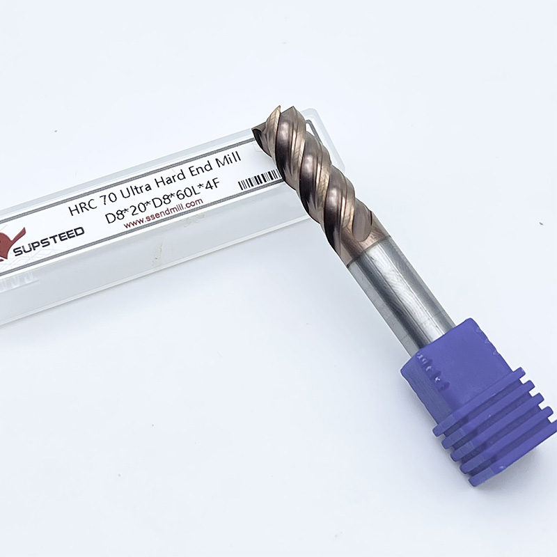
A: High-performance hard milling tools can effectively cut materials up to 70 HRC. Success at this extreme hardness requires ultra-fine micro-grain carbide, specialized TiSiN or AlTiN coatings, and highly rigid machine setups. Attempting to cut 70 HRC materials requires perfect runout control and advanced CAM toolpaths.
A: Traditional flood coolant causes rapid thermal shock. The extreme heat generated during hard milling combined with cold fluid leads to micro-fracturing along the carbide cutting edge. Use high-pressure air blasts instead to clear chips and allow the advanced coating to protect the tool.
A: Hard milling typically requires 6, 8, or even 10 flutes. Higher flute counts increase the core diameter for maximum rigidity. They also reduce the chip load per tooth, which is essential for achieving superior surface finishes on hardened materials at high feed rates.
A: Micro-grain and nano-grain carbide feature much smaller tungsten carbide particles bonded with minimal cobalt. This dense structure significantly increases the transverse rupture strength and wear resistance. Standard carbide lacks the structural integrity to withstand the extreme cutting forces of hardened steels.
A: Manual mills lack the necessary rigidity and spindle speeds. Standard VMCs can work if they possess high rigidity, minimal spindle runout, and advanced CAM capabilities. Any vibration or runout will instantly chip the brittle micro-grain carbide edges.
A: Sharp square corners create high stress concentrations and chip easily under heavy loads. A corner radius, or bull nose profile, distributes cutting forces evenly across a larger area. This geometry exponentially increases tool life and prevents catastrophic edge failure during contouring.