- All
- Product Name
- Product Keyword
- Product Model
- Product Summary
- Product Description
- Multi Field Search

Views: 0 Author: Site Editor Publish Time: 2026-08-10 Origin: Site

Machining complex internal geometries, ports, and overhanging features requires a precise balance between tool clearance and structural rigidity. Selecting the incorrect spherical wrap angle for an undercutting application frequently results in tool deflection, compromised surface finishes, shank collisions, or catastrophic tool failure, leading to scrapped parts and increased tooling costs. You cannot guess your way through steep overhangs or deep O-ring grooves. A wrong choice means pulling broken carbide out of an expensive titanium aerospace bracket or scrapping a complex mold cavity. Resolving this requires a systematic evaluation of part geometry, material hardness, machine kinematics, and chip evacuation strategies to determine whether a 220° or 270° wrap angle provides the optimal balance of reach and stability. We evaluate the exact mechanical limits of these tools so you can program feed rates confidently, prevent neck snapping, and hold tight geometric tolerances.
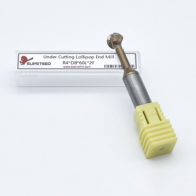
Spherical cutting tools feature a cutting edge that wraps around a central sphere. The wrap angle dictates exactly how far the flutes continue past the equator of this sphere toward the shank. A 220° tool extends slightly past the centerline, providing a moderate undercut capability. A 270° tool extends significantly further, creating a much deeper spherical profile before transitioning into the neck. This geometric distinction fundamentally alters how the tool interacts with the workpiece during multi-axis contouring. Machinists rely on undercutting end mills to machine features that standard flat or ball nose end mills cannot physically reach without colliding with the part structure. The angle you choose dictates the physical boundary of where the tool can cut versus where it will rub.
The wrap angle directly controls the maximum allowable neck diameter. There is a strict inverse relationship between the wrap angle and the structural thickness of the tool's neck. A larger wrap angle necessitates a thinner neck relief to accommodate the extended cutting edge and provide the required clearance. Because the 270° tool cuts further up the sphere, the neck must be ground down significantly to avoid rubbing against the freshly machined surface. For example, on a 0.500-inch diameter sphere, a 220° wrap might allow for a 0.250-inch neck diameter. That same 0.500-inch sphere with a 270° wrap might require the neck to be reduced to 0.125 inches. Since the stiffness of a cylinder is proportional to the fourth power of its diameter, that reduction results in a massive loss of structural rigidity. This ratio dictates the tool's moment of inertia and its ultimate resistance to bending forces.
Flute density plays a major role in managing chip evacuation within confined undercut geometries. Spherical tools typically feature between two and six flutes, depending on the sphere diameter and intended application. Two-flute configurations offer massive gullets, making them ideal for aggressive roughing in aluminum and clearing large chips from deep pockets. Four-flute configurations provide superior surface finishes in steels but restrict chip flow due to smaller gullet volumes. Six-flute tools are reserved for light finishing passes in titanium or high-temp alloys where feed rates are low and surface finish requirements are high. Chip packing remains a primary failure point in spherical geometries. When machining deep undercuts, chips easily become trapped between the tool neck and the part wall. The chosen wrap angle interacts heavily with flute density; a thinner neck on a high-angle tool provides slightly more physical room for chips to escape, but the delicate structure cannot withstand the cutting forces if chips do pack and recut.
Evaluating the success of an undercutting operation requires monitoring several distinct technical metrics. Operators must achieve specific baseline requirements to validate the process on the shop floor.
The primary advantage of a 220° wrap angle lies in its massive structural rigidity. By stopping the cutting edge shortly past the equator, the tool retains a significantly larger cross-sectional neck area. This thicker core drastically increases the tool's moment of inertia, directly reducing tool deflection under heavy radial cutting forces. When the tool engages the material, the cutting pressure attempts to push the sphere away from the cut. The robust neck of the 220° tool resists this bending moment, keeping the cutting edge precisely on its programmed path. This rigidity allows machinists to push higher feed rates, increase the depth of cut, and maintain stable machining dynamics even at extended gauge lengths. You can rough out material much faster without fear of snapping the tool.
Rigid spherical tools excel in environments demanding high material removal rates and stable cutting conditions. They are the default choice for specific heavy-duty applications across various manufacturing sectors.
Despite their strength, 220° tools face strict geometric limitations. The thick neck creates an immediate collision hazard when programming steep undercut angles. If the part geometry requires the tool to reach deep behind an overhanging ledge, the shank will inevitably strike the upper lip of the feature. This exact point of shank interference limits their utility in deep porting or complex cavity machining. Machinists cannot use these tools for aggressive back-chamfering on thick plates, as the limited wrap angle prevents the cutting edge from fully engaging the bottom edge of the hole without the neck rubbing against the bore. You must map the tool profile against the CAD model to ensure the neck clears the overhang.
When part geometry demands extreme access, 270 undercutting end mills provide the necessary clearance. The extended cutting edge wraps far up the sphere, allowing the tool to machine steep overhangs, deep O-ring grooves, and complex internal contours without shank interference. This geometry shines in continuous 5-axis toolpaths. As the machine spindle tilts and swarfs along a complex surface, the 270° wrap ensures that a sharp cutting edge remains in contact with the material, regardless of the tool axis orientation. This extended reach eliminates the need for multiple setups or custom-ground form tools, streamlining the machining of highly complex internal features. You gain the ability to reach under ledges that would otherwise require a completely different machine setup.
High-clearance spherical tools are indispensable for manufacturing intricate components across advanced industries. They tackle geometries that standard tools simply cannot reach without causing a collision.
The extreme clearance of a 270° tool comes at a severe structural cost. To accommodate the massive wrap angle, the neck diameter must be ground down to a fraction of the sphere's diameter. This reduced core makes the tool highly susceptible to deflection, bending, and catastrophic neck snapping. Even minor spikes in chip load or slight material inconsistencies can cause the delicate neck to fracture. Furthermore, the lack of rigidity makes these tools highly prone to chatter and harmonic vibration. When run at extended gauge lengths, the tool acts like a tuning fork, amplifying vibrations that degrade surface finish and rapidly chip the cutting edge. Operators must dial back feed rates and depths of cut to protect the tool.
Table 1: Technical Comparison of Spherical Wrap Angles
| Evaluation Metric | 220° Undercutting End Mill | 270° Undercutting End Mill |
|---|---|---|
| Neck Rigidity | High (Thicker Core) | Low (Thinner Core) |
| Undercut Clearance | Moderate (Shallow Angles) | Extreme (Steep Angles) |
| Deflection Risk | Low | High |
| Ideal Machining Strategy | High MRR Roughing / Finishing | Light Finishing / 5-Axis Contouring |
| Vibration Susceptibility | Low | High (Requires strict feed control) |
| Feed Rate Capability | Aggressive | Conservative |
Selecting the correct tool begins with a strict mathematical evaluation of the part geometry. Machinists must calculate the required undercut angle and the total depth of the overhanging feature. You map this part geometry directly against the tool's neck relief angle and overall reach. Stub-length configurations provide better stability but limit depth, while long-reach configurations access deep cavities but amplify deflection risks. If the undercut angle is shallow, a 220° tool easily clears the geometry. If the undercut is steep and deep, a 270° tool becomes mandatory to prevent the non-cutting shank from gouging the workpiece. Always measure the maximum radial engagement required before pulling a tool from the crib.
Material hardness dictates the maximum allowable deflection and heavily influences tool selection. Machining tough alloys like Inconel, 4140 steel, or hardened tool steels generates massive radial cutting forces. These forces will instantly snap the delicate neck of a 270° tool if pushed too hard. Therefore, harder materials strongly favor the structural stability of a 220° tool, even if it requires altering the toolpath or adding a setup. Conversely, softer materials like aluminum, brass, or engineered plastics generate lower cutting forces. In these applications, machinists can safely deploy 270° tools to maximize reach without risking catastrophic tool failure, allowing for higher material removal rates in complex geometries.
Thermal management is a major factor when operating inside confined undercut geometries. Because the cutting action occurs deep within a pocket or under a ledge, standard flood coolant rarely reaches the cutting zone. This leads to rapid heat buildup and immediate chip recutting. High-pressure coolant or through-spindle coolant systems are absolutely necessary to blast chips out of the cavity. When using high-clearance tools, preventing chip packing is your top priority; a single recut chip can snap the thin neck. Proper coolant delivery ensures thermal stability, flushes the work envelope, and protects the fragile tool structure from sudden shock loads. Programmable coolant nozzles should be aimed directly at the undercut opening.
Advanced tool coatings mitigate the intense heat generated in reduced-clearance cutting zones. Because undercutting tools often run at suboptimal surface speeds near the center of the sphere, friction is high. Coatings like Aluminum Titanium Nitride (AlTiN) or Titanium Aluminum Nitride (TiAlN) provide exceptional oxidation resistance and surface hardness, protecting the carbide substrate from thermal cracking in ferrous materials. For machining highly abrasive non-ferrous materials or composites, Zirconium Nitride (ZrN) or Diamond-like Carbon (DLC) coatings prevent built-up edge and extend tool life. Matching the coating to the workpiece material is essential for maintaining the integrity of the spherical cutting edge over long production runs.
Tool deflection directly ruins dimensional accuracy and surface finish. When a 270° tool deflects under load, it fails to cut the material to the programmed dimension, leaving excess stock and causing the tool to drag. This dragging creates a poor surface finish and makes it impossible to hold tight geometric dimensioning and tolerancing callouts. If feed rates are not properly calibrated to account for this flexibility, the part will fail inspection. The inherent rigidity of a 220° tool resists this deflection, ensuring the cutting edge remains true to the programmed path, thereby delivering superior surface finishes and reliable dimensional accuracy on the first pass.
Programming spherical geometries requires precise control over the chip load per tooth. When utilizing delicate 270° mills, programmers must drastically reduce the chip load to prevent neck failure. You cannot use standard flat end mill feed rates. Furthermore, programmers must account for radial chip thinning. Because the cutting edge is a sphere, the actual chip thickness varies depending on where the tool engages the material. If cutting near the equator, the chip is thick; if cutting near the bottom tip or high up near the neck, the chip thins out significantly. CAM software must dynamically adjust feed rates to maintain a constant, safe chip load across the entire spherical profile. Failing to adjust for chip thinning will cause the tool to rub rather than cut, leading to rapid wear.
The choice between climb and conventional milling drastically affects tool deflection in spherical geometries. Climb milling pulls the tool into the workpiece, which generally provides a superior surface finish. However, with a flexible 270° tool, this pulling force can cause the tool to over-engage and snap. In specific scenarios, conventional milling might be required to stabilize a delicate neck. Conventional milling pushes the tool away from the cut, creating a more predictable deflection pattern. Programmers often use climb milling for roughing with rigid 220° tools, and switch to light conventional milling passes when finishing delicate undercuts with high-clearance tools to prevent gouging the wall.
Undercutting operations demand rigorous digital twin simulation. Programmers must utilize advanced CAM software to perform exhaustive gouge-checking before sending code to the machine. You must accurately define the exact geometry of the cutting sphere, the neck relief, and the non-cutting shank in your tool library. The software simulates the toolpath to verify that only the flutes engage the material. If the shank rubs against an overhanging ledge, the simulation flags a collision. This digital verification is the only reliable way to ensure that the chosen wrap angle provides adequate clearance for the specific part geometry without risking a catastrophic machine crash.
In 5-axis simultaneous machining, manipulating the tool axis provides immense flexibility. By adjusting the lead (forward/backward tilt) and lag (side-to-side tilt) angles, programmers can shift the cutting contact point to the optimal zone of the sphere. Clever manipulation of the tool axis can sometimes allow a more rigid 220° tool to reach areas typically reserved for 270° tools. By tilting the spindle away from the overhanging feature, the thicker shank clears the obstruction while the spherical tip continues to cut. This programming strategy maximizes rigidity and tool life while still achieving the necessary geometric access. It keeps the cutting forces directed into the strongest part of the tool.
Tool life expectancy varies wildly between the two geometries under identical cutting conditions. A 220° tool, with its robust neck and resistance to vibration, wears predictably. Machinists typically observe standard flank wear over a long operational lifespan. Conversely, a 270° tool is highly vulnerable to micro-chipping and sudden breakage due to harmonic chatter and deflection. The hidden costs of premature tool breakage with high-clearance tools are severe. Beyond the cost of replacing the carbide, a broken tool often destroys the workpiece, leading to expensive scrap, wasted machine time, and delayed production schedules. You must factor in the risk of breakage when quoting jobs that require extreme undercuts.
Manufacturing engineers must constantly evaluate the trade-off between cycle time and process reliability. Rigid 220° tools allow for aggressive depths of cut and faster feed rates, directly lowering cycle times. However, their limited clearance might force the programmer to use multiple tools or require the operator to perform multiple part setups to reach all features. High-clearance 270° tools allow for single-setup machining, increasing positional reliability and reducing handling time. Yet, their fragile nature demands much slower feed rates and lighter passes. You must calculate whether the time saved by a single setup outweighs the time lost to conservative feed rates and potential tool failures.
The choice between 220° and 270° wrap angles is a strict compromise between tool rigidity and geometric accessibility. There is no universal solution; the correct tool depends entirely on the specific demands of the workpiece. Default to 220° tools for maximum rigidity, harder materials, and shallow undercuts to maximize material removal rates and extend tool life. Specify 270° tools only when part geometry dictates extreme clearance, primarily in complex 5-axis contouring or deep cavity work, and ensure you adjust your cutting parameters to protect the fragile neck.
A: The primary difference is the wrap angle of the spherical cutting edge, which directly dictates the thickness of the tool's neck. A 220° tool features a thicker, more rigid neck designed for heavy material removal. A 270° tool has a significantly thinner neck, providing the necessary clearance to reach into steep, deep undercuts without the shank colliding with the workpiece.
A: You should specify a 270° mill when machining deep, steep undercuts, complex 5-axis profiles, or when back-chamfering requires clearance that a thicker-necked 220° tool cannot physically provide. They are required when the part geometry would cause the shank of a 220° tool to rub or crash into the overhanging material.
A: Yes. Because they require a much thinner neck to accommodate the larger cutting angle, they possess a lower moment of inertia. This reduced core makes them significantly more susceptible to deflection, harmonic vibration, and catastrophic breakage if chip loads, feed rates, and toolpaths are not strictly controlled during programming.
A: Yes, they are highly effective in 5-axis machining environments. As long as your CAM software can tilt the tool axis enough to prevent the thicker shank from colliding with the workpiece, a 220° tool offers superior rigidity. This allows for faster feed rates and better surface finishes during simultaneous multi-axis contouring.
A: Minimize tool runout at the spindle and use the shortest possible gauge length. Select the most rigid tool allowable for the geometry, favoring a 220° over a 270° if clearance permits. Optimize your feed rates to maintain a consistent chip load, and consider using conventional milling passes when finishing delicate features to stabilize the tool.
A: Yes, "lollipop cutter" is a common industry colloquialism for a spherical undercutting end mill. Both terms refer to the exact same cutting tool, which is characterized by a spherical cutting tip mounted on a relieved neck. Manufacturers design these tools specifically for machining undercuts, complex contours, and hard-to-reach internal features.