- All
- Product Name
- Product Keyword
- Product Model
- Product Summary
- Product Description
- Multi Field Search

Views: 0 Author: Site Editor Publish Time: 2026-08-26 Origin: Site

Improper tooling selection in CNC routing carries steep hidden costs. Scrapped material, excessive manual sanding, premature tool failure, and unexpected machine downtime quickly erode shop efficiency. Operators often learn the hard way that running the wrong bit ruins expensive sheet goods and damages spindle bearings. The core issue is that wood is not a monolithic material. The structural differences between natural grain hardwoods, layered adhesives in plywood, and dense particulates found in MDF require distinct cutting geometries. Using a generic bit across all materials guarantees tear-out on veneers, friction burns on hardwoods, and edge chipping on melamine laminates. Selecting the right cnc router wood cutting tools requires a systematic evaluation framework. You must analyze material composition, desired edge finish, production volume, and material yield optimization to eliminate edge defects and maximize tooling lifespan.
Upcut bits pull wood chips upward and away from the cutting surface. This mechanical action makes them highly effective for deep pocketing and high-volume material removal. Rapid chip evacuation dissipates heat quickly, preventing friction burns inside deep channels. However, the upward pulling motion aggressively lifts the top fibers of the material. This causes severe top-edge tear-out on veneered panels and laminated boards. Furthermore, the upward force can lift smaller parts off the spoilboard if your vacuum hold-down system lacks sufficient pressure.
Downcut bits apply a downward shearing action against the material. This geometry pushes fibers down, leaving an exceptionally clean top surface. They are ideal for preserving the delicate faces of veneers and thin materials. The trade-off is poor chip extraction. Because chips are forced downward into the cut channel, the bit constantly re-cuts its own waste. You must run downcut bits at slower feed rates or take shallower passes to prevent extreme heat buildup and tool breakage. The downward force also assists in holding small parts securely against the table.
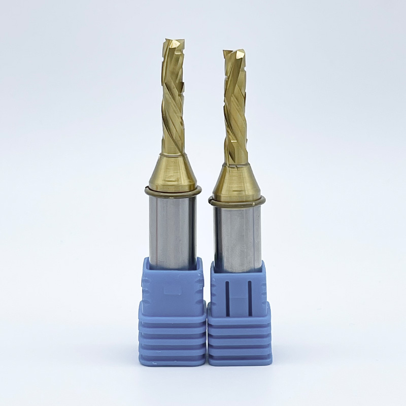
Compression bits combine both upcut and downcut flutes on a single shank. The tip features an upcut geometry, while the upper portion features a downcut geometry. This design forces chips toward the center of the material, compressing both the top and bottom faces simultaneously. They are the industry standard for cutting double-sided laminates and plywood. To achieve clean edges, the first pass must plunge deeper than the upcut portion of the bit, ensuring the downcut flutes engage the top veneer.
Straight flute bits provide a neutral cutting action. They neither pull chips up nor push them down. These bits serve as a cost-effective baseline for general-purpose routing where extreme edge quality is secondary. They clear chips moderately well but will eventually cause minor fraying on delicate top and bottom veneers as the cutting edge begins to wear.
Solid carbide stands as the absolute standard for professional CNC router bits for wood. These tools offer superior rigidity, exceptional heat tolerance, and prolonged edge retention. Engineered materials like MDF and plywood contain highly abrasive glues that destroy weaker metals. Solid carbide withstands this abrasion, maintaining a sharp cutting edge through heavy production cycles. The manufacturing process of solid carbide ensures the tool can handle the high lateral loads generated during aggressive nesting operations.
Carbide-tipped or insert tooling provides a distinct operational advantage for high-volume manufacturing. While the initial tool body requires a higher upfront investment, the long-term operational expense drops significantly. Operators simply rotate or replace the small carbide inserts when they dull, rather than discarding the entire tool. This system ensures consistent cutting diameters without the need for professional sharpening services, which alters the tool's geometry and requires CAM software adjustments.
High-Speed Steel (HSS) lacks the durability required for serious CNC production. HSS tools dull rapidly when subjected to high spindle speeds and abrasive engineered woods. Using HSS on plywood or MDF results in immediate edge degradation, burning, and ruined workpieces. Reserve HSS strictly for manual routing of softwoods or plastics where speeds remain low and heat generation is minimal.
Tool deflection occurs when lateral cutting forces bend the router bit away from its programmed path. This bending causes severe vibration, known as chatter, which ruins edge finishes and snaps tools. The physical diameter of the tool shank directly dictates its rigidity. A 1/2-inch shank offers exponentially more resistance to deflection than a 1/4-inch shank.
You must mandate 1/2-inch shanks wherever your machine collet and toolpath constraints allow. Thicker shanks absorb vibration, transfer heat more effectively into the spindle, and dramatically extend tool life. Only step down to 1/4-inch shanks when cutting intricate details that require a smaller tool radius. When setting up your tools, follow these specific guidelines to minimize deflection:
Processing dense hardwoods requires strict heat management. Natural wood features inconsistent grain density, meaning the tool encounters varying resistance throughout a single cut. If the tool dwells too long or spins too fast, friction burns the wood and destroys the tool temper. Open-grain woods like oak behave differently than tight-grain woods like maple, but both demand sharp tooling.
Deploy two-flute upcut or downcut solid carbide bits for hardwood applications. You need razor-sharp cutting edges and aggressive feed rates to maintain proper chipload. Pushing the tool faster ensures the heat transfers into the wood chips rather than building up in the tool body. Avoid compression bits on solid hardwoods unless cutting completely through the material, as the complex geometry struggles with deep pocketing in dense grain and fails to clear chips effectively.
Softwoods present a unique challenge: preventing the crushing and fuzzing of soft wood fibers while safely navigating hard, unpredictable knots. Dull tools will compress and tear softwoods rather than shearing them cleanly, leaving a fuzzy edge that requires extensive manual sanding.
Specify razor-sharp downcut bits or O-flute geometries to cleanly slice through soft fibers. The single-flute design of an O-flute provides massive chip clearance, preventing the soft material from packing into the cut channel. When handling lower-grade pine, sudden density shifts at knot locations can easily snap fragile bits. Slightly reduce your feed rates when processing knot-heavy stock to prevent catastrophic tool failure while maintaining enough speed to avoid burning.
Success with plywood demands zero tear-out on fragile top and bottom veneers while navigating highly abrasive internal glue lines. You must also maximize nesting yield to get the most parts out of a single sheet. Plywood cores often contain hidden voids that cause sudden drops in cutting resistance, leading to chatter if the tool is not rigid.
Mandate compression bits for all through-cuts on veneered panels. You must program a ramp into the cut. Plunging straight down burns the bottom veneer before the downcut portion engages the top face. Ramping allows the tool to enter smoothly. To optimize your nesting operations on sheet goods, implement these specific adjustments:
MDF consists of dense wood particulates suspended in abrasive resins. The primary goal is surviving extreme abrasion while maintaining tight dimensional accuracy over long production runs. MDF does not splinter, but it acts like a grinding wheel against carbide edges.
Solid carbide straight or downcut bits perform best in MDF. Because MDF lacks natural grain, tear-out is less of a concern, but tool wear is severe. Dust collection efficiency becomes critical here. MDF dust packs tightly into cut channels, acting as an insulator. This trapped dust rapidly increases tool temperature. Ensure your dust shoe and extraction system operate at maximum capacity to pull waste away from the cutting zone. If you see packed dust in the kerf behind the bit, your extraction is failing.
Melamine features a highly brittle plastic coating over a particleboard core. Achieving flawless, chip-free edges on both faces requires specialized geometry. Standard bits will shatter the plastic coating, resulting in rejected parts that cannot be edge-banded properly.
Specify mortise compression bits for thinner melamine sheets. Standard compression bits have an upcut section that is often too long for 1/2-inch or 5/8-inch melamine. If the upcut portion breaks the top surface, the melamine chips instantly. Mortise compression bits feature a much shorter upcut section, usually around 0.2 inches, ensuring both the top and bottom faces are actively compressed even during shallow passes.
CNC Router Bit Selection Guide by Board Material
| Board Material | Recommended Flute Geometry | Key Processing Challenge |
|---|---|---|
| Hardwoods (Oak, Maple) | Upcut or Downcut Solid Carbide | Managing heat buildup and inconsistent grain density. |
| Softwoods (Pine, Poplar) | Downcut or O-Flute | Preventing fiber crushing and navigating hard knots. |
| Plywood / Veneers | Compression (Standard) | Preventing tear-out on delicate top and bottom faces. |
| MDF | Straight or Downcut | Surviving extreme abrasion from internal resins. |
| Melamine / Laminates | Mortise Compression | Achieving chip-free edges on brittle surface coatings. |
Chipload defines the actual thickness of the wood chip removed by each cutting edge during a single revolution. The formula is straightforward: Chipload = Feed Rate / (Spindle RPM x Number of Flutes). Maintaining the correct chipload prevents tools from overheating and snapping. A proper chip carries the heat away from the tool.
A major trade-off exists between flute count and machine rigidity. Increasing the number of flutes from two to three requires a significantly higher feed rate to maintain the same chipload. If your CNC machine lacks the structural rigidity to push those higher speeds without vibrating, the tool will rub against the wood instead of cutting it. This rubbing generates massive heat, leading to rapid tool failure. Match your flute count to your machine's maximum stable feed rate. Lightweight gantry machines should stick to single or two-flute bits, while heavy industrial machines can leverage three-flute bits for maximum throughput.
The divide between hobbyist and commercial tooling is stark. Budget bits may survive weekend projects in soft poplar, but they fail rapidly under commercial nesting loads. Evaluating tooling based solely on purchase price ignores the true cost of manufacturing.
Calculate your cost-per-linear-foot. A premium solid carbide compression bit that cuts fifty sheets of melamine cleanly proves far more cost-effective than a budget bit that chips edges after ten sheets. When you factor in the cost of scrapped material, manual edge-banding repairs, and operator downtime for tool changes, investing in high-grade carbide yields massive operational savings. Track your tool life by recording the linear footage cut before edge degradation occurs, and use that data to establish a predictable replacement schedule.
Friction burns on the material indicate that the tool is rubbing rather than shearing. This heat destroys the temper of the carbide, leading to immediate dulling and potential tool breakage. You will often hear a high-pitched squealing sound when a bit is rubbing.
To mitigate heat buildup, you must increase the size of the wood chips being removed. Chips act as heat sinks, carrying thermal energy away from the tool. Increase your feed rate, decrease your spindle RPM, or switch to a tool with fewer flutes. Any of these adjustments will increase your chipload and reduce friction. Never pause the spindle while it is engaged in the material.
Plunging a compression bit directly downward pushes waste chips straight into the MDF spoilboard. Because the bottom of the bit is an upcut geometry, it traps chips against the table. This causes severe burning, ruins the spoilboard surface, and destroys the bottom tip of the router bit.
Mitigate this risk entirely within your CAM software. Program lead-ins, ramps, or helical interpolations for all plunge moves. Entering the material at an angle allows the chips to clear continuously during the initial penetration, protecting both the tool and the spoilboard. A ramp angle of 10 to 15 degrees is generally sufficient for most wood materials.
Runout occurs when the router bit spins off-center. Even a few thousandths of an inch of runout causes poor edge finishes, excessive noise, and snapped bits due to uneven chip loads on the flutes. One flute ends up doing all the cutting while the other simply rubs.
Implement strict collet maintenance schedules to eliminate runout. Follow this routine to protect your spindle and tooling:
A: A solid carbide compression bit is the best choice for plywood. It combines upcut and downcut geometries to pull the top and bottom veneers toward the center of the core. This prevents tear-out on both faces. Always program a ramped entry to prevent burning the bottom veneer during the initial plunge.
A: While possible, it is highly inefficient. MDF contains abrasive resins that require high wear resistance, making straight or downcut solid carbide ideal. Hardwood requires careful heat management and aggressive chip clearing, favoring upcut geometries. Using dedicated bits for each material significantly extends tool life and improves edge quality.
A: A beginner starter kit should include three core tools. Get a 1/4-inch downcut bit for clean top edges on general routing. Add a 1/4-inch upcut bit for deep pockets and fast chip clearing. Finally, include a 3/8-inch compression bit for cutting sheet goods without tear-out.
A: Wood burns when the router bit rubs against the material instead of cutting it. This happens due to an inadequate chipload. If your feed rate is too slow or your spindle RPM is too high, the tool generates excessive friction. Increase your feed rate or lower your RPM to create larger chips that carry heat away.
A: Upcut bits pull chips upward, offering excellent heat dissipation for deep pockets but causing tear-out on the top surface. Downcut bits push chips downward, leaving a flawless top edge but requiring slower feed rates due to poor chip extraction. Choose based on whether top surface finish or deep material removal is the priority.
A: Tool life is measured in linear feet cut, not time. Lifespan heavily depends on material abrasiveness, chipload optimization, and tool material. A solid carbide bit cutting optimized chiploads in standard plywood can last thousands of linear feet. Cutting abrasive MDF with improper speeds will dull the same bit in a fraction of the time.
A: Always use a 1/2-inch shank whenever your collet and toolpath allow. The larger diameter provides exponentially more rigidity, reducing deflection and vibration. This results in cleaner cuts, less chatter, and longer tool life. Only step down to a 1/4-inch shank when the cutting profile requires a smaller radius.