- All
- Product Name
- Product Keyword
- Product Model
- Product Summary
- Product Description
- Multi Field Search

Views: 0 Author: Site Editor Publish Time: 2026-08-28 Origin: Site

Selecting the wrong cutting tool for a specific spindle speed and machine rigidity causes catastrophic tool failure, scrapped parts, and accelerated spindle bearing wear. Machinists and production managers frequently conflate standard metalworking end mills with tooling designed specifically for gantry-style CNC routers. This mismatch in flute geometry, chip clearance, shank design, and RPM tolerance leads to suboptimal feed rates, excessive heat generation, and tool breakage.
This guide provides a technical evaluation of router end mills versus standard end mills, analyzing tool geometries, machine dynamics, material composition, and material-specific success criteria to ensure optimal tooling procurement for your CNC setup.
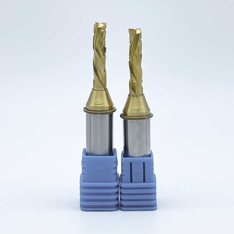
Router tooling features distinct structural characteristics tailored specifically for high-speed gantry applications. These cutters typically incorporate one to three flutes. Tool engineers design them with straight or specialized helical geometries to manipulate how the material shears and where the chips flow. The primary design intent focuses entirely on rapid chip evacuation at extreme spindle speeds. Evacuating chips instantly prevents heat buildup, which ruins softer materials like plastics and wood.
Shank dimensions follow standard fractional or metric sizing, most commonly 1/4-inch, 3/8-inch, and 1/2-inch diameters. These shanks are precision-ground to h6 tolerances to perfectly match standard ER router collet systems. Material composition dictates the tool's operational lifespan and application.
Manufacturers engineer CNC router bits to handle the unique demands of machines where spindle speeds routinely exceed 18,000 RPM. They prioritize massive chip clearance over absolute core rigidity. A thick core simply gets in the way when you need to eject large volumes of lightweight material.
Standard end mills serve as the backbone of traditional metalworking and heavy material removal. They feature dense flute counts, typically ranging from three to six, with specialized roughing tools sometimes featuring even more. Tool designers build them with variable helix angles and exceptionally thick core diameters. The primary design intent maximizes absolute rigidity. High rigidity minimizes chatter and extends tool life under heavy radial chip loads in dense materials like steel and titanium.
Shank sizing follows strict industrial standards tailored for heavy-duty tool holders. Many feature Weldon flats designed for set-screw holders to prevent pull-out under massive torque. They also maintain precise cylindrical tolerances for compatibility with hydraulic milling chucks and shrink-fit systems. Material compositions differ from router tooling to handle extreme heat and impact.
Standard end mills prioritize core strength above all else. They must withstand massive radial cutting forces generated when plowing through solid metal blocks on rigid machining centers.
The relationship between flute count, chip pocket size, and feed rate dictates machining success. Tool designers must balance core strength with chip clearance. Lower flute counts create larger chip pockets, known as gullets. Larger gullets allow massive volumes of material to escape the cutting zone rapidly. Higher flute counts increase the tool's core strength but drastically reduce the available space for chip ejection.
High flute counts fail catastrophically in CNC routers. If you run a four-flute or six-flute tool at 18,000 RPM, the machine leaves insufficient time and physical space for chip ejection. The chips remain trapped in the flute valleys. The tool recuts these trapped chips, generating massive friction. In plastics, this friction causes immediate melting. In wood, it causes burning. In aluminum, the chips weld directly to the carbide, snapping the tool instantly.
Standard end mill helix angles typically range from 30 to 45 degrees. Manufacturers often utilize variable pitch and variable helix designs. These variable geometries disrupt harmonic frequencies during heavy metal cutting. Disrupting these frequencies eliminates chatter, prevents tool breakage, and improves surface finish on rigid milling machines.
Router-specific geometries focus on material control rather than harmonic dampening. They utilize distinct spiral directions to manage the workpiece and prevent surface damage.
Web thickness determines a tool's resistance to deflection. Standard end mills prioritize a massive, thick core. This thick core resists bending under the extreme radial loads encountered when roughing solid steel. The thick core prevents micro-chipping of the cutting edge and ensures dimensional accuracy on deep vertical walls.
Router tools intentionally sacrifice core thickness. They require massive chip gullets to evacuate soft, stringy materials. Because gantry routers take lighter radial depth of cuts at much higher speeds, the reduced core thickness rarely causes deflection issues in soft materials. However, this thin core makes them entirely unsuitable for machining hard metals. If you push a router bit into steel, the core will flex and snap immediately.
Most standard end mills feature center-cutting geometry. One or more cutting edges extend completely to the center of the tool axis. This allows the tool to plunge vertically into the workpiece exactly like a drill bit. Center-cutting capability is required for traditional pocket milling in metal where the tool must enter the center of a solid block.
Many CNC router bits lack true center-cutting geometry. Plunging them straight down damages the bottom edge, burns the material, and risks starting a fire in wood dust. Operators must use specific toolpath strategies to enter the material safely. Ramping enters the material at a shallow angle, typically 2 to 5 degrees. Helical interpolation spirals the tool down into the cut. Both methods reduce vertical cutting forces and evacuate chips efficiently during entry.
Machine architecture dictates tool selection. Gantry CNC routers utilize high-speed electro-spindles. These spindles operate effectively between 10,000 and 24,000 RPM. They deliver very low torque at lower speeds, meaning they will stall if pushed hard below 8,000 RPM. Vertical Machining Centers (VMCs) utilize gear-driven or belt-driven spindles. They operate effectively between 4,000 and 12,000 RPM. They deliver massive torque across their entire speed range, allowing them to push large tools through tough materials.
Surface Footage per Minute (SFM) dictates the required RPM for a specific tool diameter and material. The formula is SFM = RPM × Diameter × 0.262. Soft materials require high SFM, demanding the high RPMs of a router. Hard metals require low SFM, demanding the low RPMs and high torque of a VMC. Running a standard end mill at router speeds exceeds its designed SFM, burning the cutting edge instantly. Conversely, running a router bit at low VMC speeds often results in rubbing rather than cutting.
The mass and rigidity of the machine frame directly impact tool life. VMCs utilize massive cast-iron frames weighing several tons. These frames absorb vibration and resist cutting forces. Standard end mills require this extreme rigidity. Any vibration causes micro-chipping along the brittle carbide cutting edge, destroying the tool.
Gantry routers utilize lighter welded steel or aluminum frames. They inherently lack the vibration-dampening mass of a VMC. Toolpath strategies must adapt to this lighter architecture to prevent chatter.
Achieving the correct chip load prevents tool failure. Chip load represents the physical thickness of the material removed by each cutting edge per revolution. You must match feed rate, RPM, and flute count to achieve the target chip load for your specific material.
The formula is: Feed Rate = RPM × Number of Flutes × Target Chip Load. For example, if you want a 0.015-inch chip load using a 2-flute tool at 18,000 RPM, your feed rate must be 540 inches per minute (18,000 × 2 × 0.015). If the chip load is too small, the tool rubs against the material instead of cutting it. This generates massive heat and dulls the edge. If the chip load is too large, the cutting forces exceed the core strength of the tool, snapping the cutter. Router operators must maintain high feed rates to match their high spindle speeds and achieve proper chip loads.
Wood and engineered composites present unique machining challenges. Wood features a directional cellular grain structure. Cutting against this grain causes splintering and tear-out. MDF contains highly abrasive glues and resins that rapidly dull standard cutting edges, requiring specialized carbide grades.
Compression and down-cut geometries are the only viable choices for these materials. A down-cut tool shears the wood fibers downward, leaving a pristine top edge. A compression tool shears both the top and bottom edges inward. This prevents delamination on double-sided melamine or veneered plywood. Standard end mills lack these specialized shearing angles. They will destroy the surface finish of laminated composites, leaving jagged edges that require manual sanding.
Machining plastics requires aggressive heat management. Plastics possess low melting points. Friction in the cutting zone causes the material to melt rather than chip. This melted plastic wraps around the tool, a phenomenon known as chip welding, which ruins the part and breaks the cutter.
Standard end mills cause immediate chip welding in plastics. Their high flute counts do not provide enough clearance for the bulky plastic chips. Single-flute "O-flute" designs serve as the industry standard for plastics. The O-flute geometry provides a massive, polished chip gullet. It delivers a sharp, slicing action that ejects the chip before it can absorb heat and melt. You must pair O-flute tools with aggressive feed rates to ensure the heat transfers into the chip, not the workpiece.
Non-ferrous metals represent a crossover zone between routing and traditional milling. Aluminum is soft and gummy. It requires sharp cutting edges and excellent chip evacuation to prevent galling. You must evaluate machine rigidity, spindle horsepower, and coolant availability when selecting tools for aluminum.
Ferrous metals demand extreme rigidity and specialized tool geometries. Router tools fail immediately in these materials. They lack the necessary core strength. Their cutting edges are too sharp and fragile to withstand the impact forces of machining steel, causing the edge to shatter on contact.
Standard end mills are absolutely necessary for ferrous metals. Manufacturers apply specific edge preparations, such as a microscopic hone or T-land, to strengthen the cutting edge against impact. They utilize advanced coatings like AlTiN (Aluminum Titanium Nitride) or TiAlN. These coatings thrive in high-heat environments. They form a protective aluminum oxide layer that shields the carbide substrate from the extreme temperatures generated during steel machining.
Tooling Geometry and Application Comparison
| Feature | Router End Mills | Standard End Mills |
|---|---|---|
| Optimal Spindle Speed | 10,000 - 24,000+ RPM | 4,000 - 12,000 RPM |
| Flute Count | 1 to 3 Flutes | 3 to 6+ Flutes |
| Core Thickness | Thin (Maximizes Chip Clearance) | Thick (Maximizes Rigidity) |
| Primary Materials | Wood, Plastics, Composites, Aluminum | Steel, Titanium, Cast Iron, Hard Alloys |
| Specialized Geometries | Up-cut, Down-cut, Compression, O-Flute | Variable Helix, Center-Cutting, Corner Radius |
Common Machining Defects and Tooling Solutions
| Defect Observed | Probable Cause | Tooling Solution |
|---|---|---|
| Melted Plastic Edges | RPM too high, feed rate too low, too many flutes. | Switch to a single O-flute tool, increase feed rate. |
| Tear-out on Top Veneer | Up-cut geometry lifting the wood fibers. | Switch to a down-cut or compression geometry. |
| Tool Snapping in Aluminum | Chip packing in the gullets, lack of lubrication. | Use a polished single-flute tool, add air blast/mist. |
| Burn Marks on Wood | Tool rubbing due to low feed rate or dull edge. | Increase feed rate to achieve proper chip load, replace tool. |
High RPMs and aggressive feed rates generate significant axial forces. Up-cut spiral geometries naturally pull the tool downward into the material. This pulling action creates a severe risk of the tool slipping out of the collet during operation. Tool pull-out ruins the workpiece, destroys the tool, and damages the machine spoilboard.
Mitigating this risk requires strict tool holding protocols. You must perform regular collet maintenance. Clean the collet and the spindle taper with a specialized wiper before every tool change. Adhere strictly to the manufacturer's torque specifications when tightening the collet nut. Avoid using shank adapters or reducing sleeves, as they introduce runout and decrease gripping force. Always utilize high-precision ER collets matched exactly to the tool's shank diameter. Snap the collet into the nut before threading it onto the spindle to ensure proper seating.
Aggressive cutting geometries impact workholding stability. Up-cut geometries exert a strong upward lifting force on the workpiece. When machining thin or lightweight materials on a vacuum table, this lifting force easily overcomes the vacuum hold-down pressure. The part lifts, shifts, and is subsequently destroyed by the cutter.
You must adapt your tooling and workholding strategies to prevent part lift. Utilize down-cut or compression geometries when cutting thin sheet goods. These geometries push the material down against the spoilboard, reinforcing the vacuum hold. Ensure your vacuum pump delivers adequate CFM for the porousness of your spoilboard. Implement mechanical clamps, double-sided tape, or composite nailers for small parts that lack sufficient surface area for vacuum holding. Zone your vacuum table properly to concentrate suction directly under the workpiece.
Selecting the correct cutting tool dictates the success of any CNC operation. Applying standard metalworking tools to high-speed routing environments guarantees failure. You must align your tooling choices with your machine's specific architectural capabilities. Follow these actionable steps to optimize your machining process.
A: No. Standard end mills lack the necessary chip clearance for wood. Their high flute counts cause rapid chip packing. This leads to severe friction, material burning, and immediate tool breakage at high router RPMs.
A: Up-cut geometries pull chips upward. This allows for faster feed rates but risks lifting the material off the table. Down-cut geometries push chips downward. This leaves a clean top surface finish but requires slower feed rates to prevent chip packing.
A: Melting occurs due to excessive friction and poor chip evacuation. Using a tool with too many flutes or running at an RPM that is too high causes chip welding. Switch to a single-flute O-flute design and increase your feed rate.
A: Compression bits are designed primarily for double-sided laminated materials and plywood. While they can cut solid wood, standard up-cut or down-cut tools often provide better chip clearance for deep solid wood profiling operations.
A: Replace precision ER collets every 400 to 600 hours of spindle operation. Worn collets introduce microscopic runout. This runout causes vibration, poor surface finishes, and premature tool breakage.
A: Many router bits lack center-cutting geometry. Plunging straight down crushes the bottom of the tool. You must use ramping or helical interpolation toolpaths to enter the material safely and evacuate chips during entry.