- All
- Product Name
- Product Keyword
- Product Model
- Product Summary
- Product Description
- Multi Field Search

Views: 0 Author: Site Editor Publish Time: 2026-08-16 Origin: Site
Maximizing Material Removal Rates (MRR) during heavy milling operations presents a persistent engineering challenge in CNC machining. Machinists constantly balance aggressive material removal against catastrophic tool failure, spindle wear, and excessive chatter. Prolonged cycle times and high tooling replacement costs severely impact shop throughput when using standard solid carbide tools for bulk material removal. Pushing traditional tools too hard inevitably leads to broken flutes, scrapped parts, or stalled machine spindles.
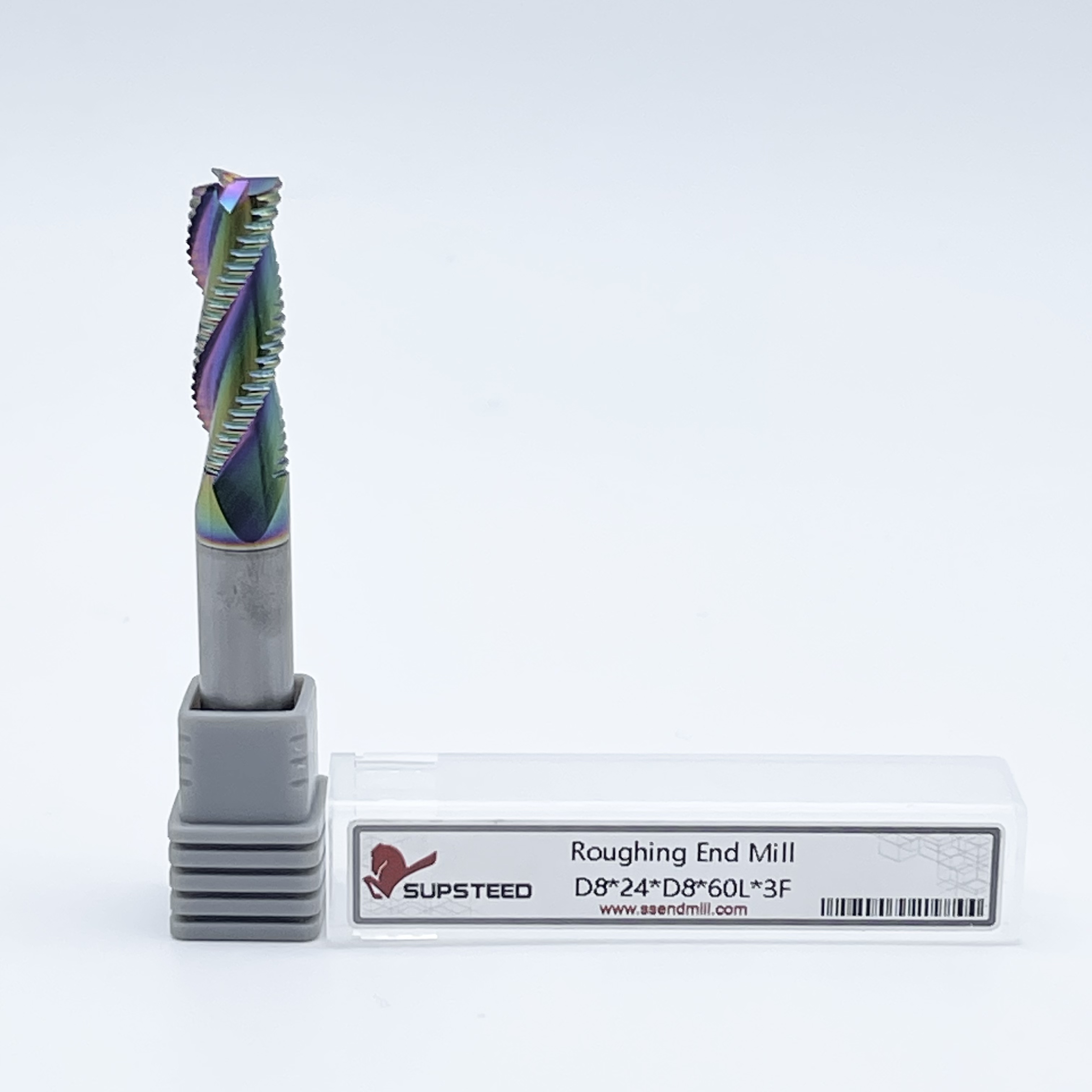
The engineered solution for high-efficiency roughing lies in carbide rougher end mills, commonly known on the shop floor as "hoggers." Their specific serrated geometry fundamentally alters chip formation and machining economics. By breaking continuous chips into small, manageable segments, these tools drastically reduce cutting resistance and dissipate heat rapidly. We will look at how their specific geometry fundamentally alters chip formation and machining economics.
The defining characteristic of any roughing tool is its scalloped or serrated cutting edge. This geometry alters the physics of the cut at the point of contact. When a standard end mill engages a workpiece, it peels a continuous ribbon of metal. In deep pockets, this continuous chip takes up significant space in the flute gullet. If the chip cannot escape, it recuts, packs into the flute, and eventually snaps the tool. The serrations on a rougher fracture the material into short, distinct segments. This fundamental change prevents chips from packing, facilitating rapid evacuation through the flutes and out of the cutting zone.
Tool manufacturers utilize two primary serration profiles to handle different material hardness levels. Sinusoidal, or wavy, profiles provide a smooth shearing action. This geometry works exceptionally well for general-purpose machining in mild steels, cast iron, and 400-series stainless steels. Flat-crested, or knuckle, profiles feature flattened peaks that maximize the volume of carbide directly behind the cutting edge. The knuckle profile resists micro-chipping under extreme mechanical loads. You need this specific profile when machining hardened D2 tool steels or aerospace superalloys where edge retention dictates tool life.
Standard flutes experience continuous cutting pressure along the entire engaged length of the tool. This continuous engagement generates massive radial forces, pushing the tool away from the workpiece. This deflection induces chatter, leaving poor finishes and destroying spindle bearings. The serrated edges of roughers create an interrupted cutting action. Only the peaks of the serrations engage the material at any given microsecond. This distributes the cutting force and drastically lowers the overall radial load on the spindle.
Modern roughing end mills integrate variable helix angles and asymmetrical flute spacing alongside these serrations. By altering the angle of each flute—for example, alternating between 35 and 38 degrees—the tool disrupts harmonic frequencies. Chatter is simply mechanical resonance building up during the cut. By breaking that resonance through geometric asymmetry, the tool virtually eliminates chatter even at maximum depths of cut. This interrupted cut maximizes machine horsepower utilization, allowing smaller 40-taper machines to take heavier cuts without stalling the spindle motor.
Success in deep pocketing and heavy slotting operations depends entirely on chip evacuation and tool stability. When plunging into solid material to cut a slot, the tool experiences 180 degrees of radial engagement. Chips easily jam in this confined cutting zone, leading to immediate tool breakage with standard end mills. Roughers handle this aggressive engagement because the fractured chips flow freely up the gullets. They maintain rigid stability at higher depths of cut (DOC) and widths of cut (WOC). Machinists can utilize the entire flute length for axial engagement, removing massive volumes of material in a single pass rather than programming multiple shallow step-downs.
Machining Titanium (Ti-6Al-4V), Inconel 718, and austenitic stainless steels introduces severe thermal challenges. These materials exhibit low thermal conductivity and tend to work-harden rapidly ahead of the cutting edge. Heat pools at the tool rather than dissipating into the chip, causing rapid degradation of the carbide substrate. The interrupted cut of a rougher manages thermal transfer efficiently. The serrations allow brief cooling intervals between engagements. The heat transfers into the small, fractured chip, which is immediately evacuated from the cutting zone. This prevents the workpiece material from work-hardening and extends the life of the cutting edge.
Aerospace and automotive manufacturing frequently require ultra-high-feed hogging of 6061 and 7075 aluminum blocks. For these applications, machinists rely on 3-flute, high-helix roughers designed specifically for non-ferrous materials. Aluminum is notoriously soft and gummy. It is highly prone to Built-Up Edge (BUE), a condition where the material pressure-welds itself to the cutting tool. Aggressive chip breakers and highly polished flutes on these specific roughers prevent BUE and galling. The coarse pitch provides massive gullets, allowing for extreme feed rates that turn solid aluminum billets into structural aerospace components rapidly.
Tool deflection becomes a critical failure point in extended-reach scenarios, such as deep cavity mold making. As the length-to-diameter ratio increases, the tool acts like a lever. It bends away from the cut, causing severe dimensional inaccuracies, tapered walls, and heavy chatter. Because roughers inherently generate lower radial cutting forces due to their serrated geometry, they reduce this bending moment. The tool stays straighter during the cut. They remain the standard choice for deep cavity roughing where rigidity is inherently compromised by the required tool length.
Selecting the correct pitch profile directly dictates tool life and chip evacuation efficiency based on the workpiece material. The pitch refers to the distance between the serrations on the cutting edge.
Flute count dictates the balance between core strength and chip clearance. A proper decision framework relies on the target material. A 3-flute geometry is mandatory for non-ferrous materials and aluminum, providing the massive gullet space required to evacuate large volumes of chips at high speeds. For ferrous metals, mild steels, and high-temp alloys, 4-to-6+ flutes are necessary. The higher flute count increases the core diameter of the tool. A thicker core provides the immense rigidity required to withstand heavy feed rates in tough materials without snapping the tool at the shank.
Uncoated carbide degrades rapidly under the extreme heat of heavy roughing in ferrous metals. Industry-standard Physical Vapor Deposition (PVD) coatings protect the carbide substrate. Aluminum Titanium Nitride (AlTiN) and Titanium Aluminum Nitride (TiAlN) are standard for ferrous machining. Under high heat, these coatings form a microscopic aluminum oxide layer that acts as a thermal barrier. When machining steel dry, AlTiN coatings excel by utilizing the heat of the cut to activate this oxidation layer. For aluminum, Zirconium Nitride (ZrN) or Titanium Carbonitride (TiCN) provides the necessary lubricity to prevent material adhesion during flood coolant applications.
Pitch Profile Selection Guide
| Pitch Type | Target Material | Chip Size | Primary Benefit |
|---|---|---|---|
| Fine Pitch | Titanium, Inconel, Hardened Steels | Small, granular | Maximum edge strength, even wear distribution |
| Medium Pitch | Carbon Steels, Cast Iron, Alloy Steels | Medium, segmented | Balanced performance for general job shop use |
| Coarse Pitch | Aluminum, Brass, Plastics, Mild Steel | Large, broken | Maximum chip evacuation, prevents flute packing |
Follow these steps to evaluate your tooling needs before programming your next job:
Solid carbide roughers carry a higher upfront cost premium compared to standard end mills. Analyzing this cost in isolation ignores machine economics. The measurable reduction in machine cycle times easily offsets the initial purchase price. If a heavy pocketing operation takes forty minutes with a standard tool and fifteen minutes with a rougher, the shop reclaims twenty-five minutes of machine time per part. This drastic increase in overall shop throughput maximizes hourly machine rate profitability. You can run more parts per shift, turning the tooling investment into immediate financial gains on the production floor.
The economics of regrinding carbide roughers significantly extend their lifecycle value. Professional tool grinders can resharpen the serrated edges multiple times. Machinists must account for dimensional changes after this process. Resharpening grinds the face of the flute, which reduces the outer diameter (OD) of the tool and slightly alters the pitch profile. To maintain accuracy and prevent scrap, the CNC programmer must measure the reconditioned tool precisely. They must update the tool diameter offset data within the CAM software and the machine control. Proper management of reground tools ensures maximum return on the initial investment.
The primary limitation of roughing tools is the resulting surface finish. They will always leave visible witness marks, commonly referred to as a corduroy effect, on the walls and floor of the workpiece. Machinists must explicitly factor this compromise into their process planning. You cannot use a rougher for a finished wall. The CAM strategy must include a tool change and a dedicated finishing pass. Programmers typically leave 0.010 to 0.020 inches of radial and axial stock during the roughing cycle. This allows a standard solid carbide end mill to clean up the striated surface and achieve final dimensional tolerances.
Aggressive MRR generates extreme axial forces. The helix angle of the tool acts like a screw, actively pulling the end mill out of the holder during heavy cuts. Standard ER collets lack the gripping force required to counteract this pull-out risk. If the tool pulls out, it cuts too deep, leading to scrapped parts and damaged machine tables. High-security tool holding solutions are mandatory. Machinists should utilize heavy-duty milling chucks, shrink-fit holders, or shanks equipped with Weldon flats and set screws. These mechanical locking mechanisms physically prevent the tool from migrating downward during aggressive hogging operations.
Using traditional offset toolpaths with roughers introduces severe risks. Traditional paths often force the tool into tight corners, suddenly spiking radial engagement to 100%. This spikes the cutting load and snaps the tool instantly. Modern CAM strategies, specifically Trochoidal milling and High-Efficiency Milling (HEM), mitigate this risk. These dynamic toolpaths maintain a constant radial chip load by utilizing circular motions and low stepovers, typically 10% to 15% of the tool diameter. They combine this light radial engagement with massive axial depths of cut. This strategy utilizes the entire serrated edge, maximizing tool life and preventing sudden load spikes.
Applying flood coolant incorrectly during heavy interrupted cuts destroys carbide tools. When machining steels and high-temp alloys, the cutting edge heats up rapidly during engagement and cools instantly when it exits the cut. Blasting this superheated carbide with cold flood coolant causes severe thermal shock. The carbide micro-fractures, leading to premature edge failure. For heavy steel milling, machinists must use high-pressure air blast to clear chips while allowing the coating to manage the heat. Conversely, when machining aluminum, high-pressure flood coolant is strictly required to provide lubricity and prevent the gummy material from welding to the flutes.
A: No. The serrated cutting edge inherently leaves a rough, grooved surface finish known as a corduroy effect. You must leave a small amount of stock material and use a standard solid carbide end mill for the final finishing pass to achieve precise dimensional tolerances and smooth surface requirements.
A: Fine pitch tools feature more serrations per inch, providing higher edge strength ideal for hard materials like titanium and tool steel. Coarse pitch tools have fewer, larger serrations, creating massive chip clearance necessary for softer, gummy materials like aluminum to prevent flute packing.
A: While the spindle RPM might remain similar, feed rates and axial depth of cut can often be increased by 20% to 50%. The exact increase depends heavily on machine rigidity, tool holding security, and the specific material being machined.
A: Yes. The interrupted cutting action created by the serrations requires less horsepower to shear the material. This significantly reduces radial forces pushing against the spindle, lowering overall load and extending the lifespan of the machine's spindle bearings.
A: Yes, for modern CNC applications. Carbide offers significantly higher heat resistance and rigidity, allowing for much faster surface footage and longer tool life. However, HSS roughers may still be appropriate for older, less rigid manual machines where carbide might chip under vibration.
A: Yes, they can be reground by professional tool grinders to restore the cutting edge. However, this process reduces the outer diameter of the tool. The CNC programmer must carefully update the tool offset data in the machine control to maintain accurate cutting dimensions.
A: They are highly effective across all material types, but they provide the highest return on investment when machining difficult-to-machine alloys. They excel in Titanium, Inconel, austenitic stainless steel, and hardened tool steels where standard end mills fail rapidly.