- All
- Product Name
- Product Keyword
- Product Model
- Product Summary
- Product Description
- Multi Field Search

Views: 0 Author: Site Editor Publish Time: 2026-08-28 Origin: Site

Tool failure, scorched materials, and poor surface finishes rapidly inflate operational costs on the shop floor. These issues frequently stem from a single, avoidable error: mismatching cutting tool geometry with high-speed routing applications. Manufacturers and fabricators constantly face the challenge of balancing aggressive Material Removal Rates (MRR) with the strict requirement for pristine edge finishes. This balancing act becomes particularly difficult when processing softer materials, engineered plastics, and non-ferrous metals. Standard woodworking bits often lack the structural integrity for heavy material removal, while rigid metal-cutting tools fail at high spindle speeds because they cannot clear chips fast enough.
You need an engineered solution that bridges the gap between traditional edge-shaping router bits and heavy-duty machine shop tooling. router end mills provide this exact balance. They combine the plunging and slotting capabilities of traditional end mills with the high-shear, massive chip evacuation geometry required by high-RPM spindles. Understanding how to evaluate and deploy these specialized cutting tools directly impacts your production efficiency, part quality, and overall machining capabilities.
Understanding the structural anatomy of a cutting tool is the first step in proper selection. A standard routing tool consists of a shank, a cutting diameter, an overall length (OAL), a cutting edge length (CEL), and a specific flute geometry. The shank must maintain strict dimensional tolerances to ensure proper seating within the collet. If a collet has even 0.002 inches of runout, a single-flute tool takes the entire cutting load unevenly, causing premature wear and poor edge finish. The cutting diameter determines the width of the slot or profile, while the overall length dictates the maximum reach of the tool.
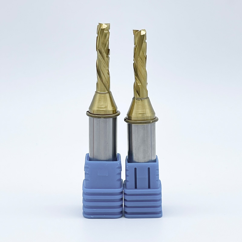
You can visually distinguish these specialized tools from traditional side mill bits or standard metal end mills by examining the chip gullets. The gullets on routing tools are significantly wider, deeper, and often highly polished. This open architecture facilitates the rapid ejection of large chips generated when cutting wood, plastic, or aluminum. Additionally, you will notice specific helix angles tailored to lift or push chips efficiently, alongside a smooth shank-to-flute transition that enhances overall tool rigidity. The high-shear cutting edge is intentionally designed to slice cleanly through softer materials at high RPMs, reducing cutting forces and preventing material deformation.
When inspecting a new tool on the shop floor, follow these visual checks:
The operational differences between these two tool categories dictate how you program your toolpaths. Standard router bits primarily excel at profiling and edge shaping. They often feature pilot bearings or non-cutting centers, restricting them to lateral movements along the edge of a workpiece. In contrast, end mills are center-cutting tools. They possess cutting edges that extend all the way to the center of the tool's face. This geometry allows them to plunge straight down into the material like a drill before moving laterally to create a slot, pocket, or complex 3D contour.
Depth of cut represents another major distinction. Standard profiling bits are generally limited to shallow passes. Conversely, continuous flute designs enable end mills to achieve significantly deeper cut depths in a single pass. The flutes continuously channel chips up and out of the deep trench, preventing chip packing and heat buildup. Furthermore, solid carbide end mills offer vastly superior structural rigidity compared to brazed carbide-tipped router bits. A brazed bit consists of a steel body with a small piece of carbide welded to the edge. Solid carbide tools are ground from a single blank, minimizing deflection under heavy loads and allowing manufacturers to utilize exact fractional or metric sizing for high-precision slotting.
A common error in many fabrication shops is the belief that standard machine shop end mills will perform adequately in wood or plastic routers. This assumption ignores the fundamental physics of high-speed machining. Standard steel-cutting end mills typically feature four, five, or even six flutes. They are engineered to take thousands of tiny slivers per minute at relatively low spindle speeds (often under 5,000 RPM) while flooded with liquid coolant.
When you place a 4-flute steel-cutting tool into a router spinning at 18,000 RPM, you encounter the tight spiral problem. The tight helix angles and shallow chip gullets cannot evacuate the large, stringy chips produced by wood or plastic. The tool begins recutting its own chips. Friction spikes immediately. The material burns, melts, or scorches, and the tool often snaps due to excessive heat and chip packing. However, there is a notable crossover exception. Aluminum-cutting end mills, which typically feature a high helix angle and two to three flutes, often perform exceptionally well in routing applications. Their geometry is explicitly designed for aggressive chip evacuation, making them highly effective for machining hard plastics and dense woods where clearing debris quickly is the primary goal.
Machining non-ferrous metals like aluminum, brass, and copper demands specific tool geometries to prevent tool failure. Aluminum, in particular, is notorious for its gummy nature. During high-speed milling, aluminum chips tend to heat up and weld themselves directly to the cutting edge of the tool. This phenomenon is known as galling. Once galling occurs, the tool stops cutting and starts plowing through the material, leading to immediate breakage and ruined parts.
To combat this, operators rely on specialized O-flute or high-helix routing end mills. The O-flute design features a single, massive flute that curls the chip and ejects it forcefully, preventing the heat buildup that causes chip welding. High-helix designs aggressively lift the chips out of deep slots. When executing deep slotting operations in non-ferrous metals, combining these specialized geometries with proper Minimum Quantity Lubrication (MQL) or mist coolant ensures clean cuts, extended tool life, and accurate part dimensions. You must keep the chip moving and the cutting edge lubricated to succeed in aluminum routing.
The plastics and composites industry presents unique machining challenges that require highly specific tooling approaches. Acrylics are highly prone to melting and recasting behind the tool if the feed rate is too slow or the chip clearance is inadequate. Cast acrylic tends to chip nicely, while extruded acrylic melts almost instantly if the tool rubs. Polycarbonates can gum up the cutter and require very sharp cutting edges. High-Density Polyethylene (HDPE) produces long, continuous strings that wrap around the spindle, requiring tools that break the chip effectively. Carbon fiber is incredibly abrasive and destroys standard cutting edges in minutes.
The primary success criterion in plastic fabrication is achieving a clear, polished edge directly off the machine. Secondary finishing operations, such as manual sanding or flame polishing, add unacceptable labor costs. Single-flute tools excel here by providing maximum chip clearance, keeping the cutting zone cool. For abrasive composites like carbon fiber, specialized multi-flute diamond-cut routers or heavily coated solid carbide tools are necessary. These tools shear the rigid fibers cleanly without causing delamination, even at deep cut depths.
Best practices for routing plastics include:
Modern panel processing relies heavily on engineered woods like Medium Density Fiberboard (MDF), Baltic birch plywood, and various dense hardwoods. These materials often feature abrasive glues and resins that dull cutting tools rapidly. Traditional straight-flute bits struggle to maintain clean edges on these laminated or veneered surfaces, often causing tear-out on either the top or bottom face.
Compression tools solve this problem for panel processing. A compression tool combines both up-cut and down-cut geometries on the same cutting edge. The bottom portion of the flute pulls the material upward, while the top portion pushes the material downward. This opposing action compresses the material toward the center of the core. When cutting double-sided melamine or veneered plywood, a compression tool eliminates chipping and tear-out on both faces simultaneously during full-depth profile cuts. This yields perfectly clean parts ready for edge-banding directly off the CNC machine. For shallow pockets where a standard compression tool would pull up the top veneer, operators use a "mortise compression" bit, which features a much shorter up-cut section at the tip.
Selecting the correct flute count is a direct response to the material you are cutting and the capabilities of your machine. The flute count dictates the volume of the chip gullet and the feed rate required to maintain a proper chipload. If you choose a tool with too many flutes for your machine's maximum feed rate, the tool will rub, generate heat, and fail.
The direction of the spiral flute determines where the chips go and how the cutting forces interact with your workpiece. Mastering cut direction is essential for achieving clean edges and maintaining part stability on the machine bed.
Tool Cut Direction and Edge Finish Comparison
| Cut Direction | Chip Evacuation | Top Edge Finish | Bottom Edge Finish | Primary Use Case |
|---|---|---|---|---|
| Up-Cut | Excellent (Upward) | Prone to tear-out | Clean and smooth | Deep slotting, thick materials, plunging, aluminum |
| Down-Cut | Poor (Downward) | Clean and smooth | Prone to tear-out | Thin sheets, shallow pockets, delicate top veneers |
| Compression | Moderate (Trapped in center) | Clean and smooth | Clean and smooth | Double-sided laminates, melamine, plywood panels |
The substrate material of the cutting tool determines its baseline durability and rigidity. High-Speed Steel (HSS) is highly affordable and possesses a sharper initial edge than carbide. However, HSS dulls rapidly when exposed to the abrasive resins in MDF, the hard glue lines in plywood, or the heat generated by high-speed routing. Solid carbide is the professional standard for CNC operations. It withstands extreme temperatures, maintains its edge far longer, and provides the necessary rigidity to prevent deflection during heavy cuts.
Specialized coatings further enhance solid carbide performance by altering the surface properties of the tool. Zirconium Nitride (ZrN) is a popular coating for machining aluminum and plastics. It significantly increases the lubricity of the tool, preventing chip welding and galling by allowing chips to slide out of the gullet effortlessly. Diamond-Like Carbon (DLC) coatings offer extreme hardness and a very low coefficient of friction, extending tool life dramatically when machining highly abrasive materials like fiberglass or carbon fiber. Aluminum Titanium Nitride (AlTiN) excels in high-heat applications, forming a protective aluminum oxide layer during the cut that shields the carbide substrate from thermal shock.
The most common cause of tool failure and poor surface finish is an incorrect chipload. Chipload refers to the physical thickness of the chip removed by each cutting edge per revolution. If your feed rate is too slow relative to your spindle RPM, the tool generates fine dust or tiny slivers instead of proper chips. Dust cannot carry heat away from the cutting zone. Consequently, the heat transfers directly into the tool and the workpiece, leading to burnt wood, melted plastics, and snapped cutters.
To calculate the optimal feed rate, you must use a strict mathematical framework based on the tool's geometry and the spindle's capabilities. The formula is: Feed Rate (Inches Per Minute) = RPM × Number of Flutes × Target Chipload. For example, if you are running a 2-flute tool at 18,000 RPM with a target chipload of 0.015 inches, your required feed rate is 540 IPM (18,000 x 2 x 0.015). If your machine can only reliably cut at 200 IPM, you must either drop your RPM to 6,600 (which may stall the spindle) or switch to a 1-flute tool to maintain a healthy chipload. By aligning your machine's feed rate with the specific flute count, you ensure the tool shears the material efficiently.
Listening to the cut is also a valid shop-floor diagnostic. A high-pitched scream indicates rubbing, meaning your feed rate is too slow or your RPM is too high. A deep, aggressive growl indicates a heavy load, meaning your feed rate is too fast or your RPM is too low. A smooth, consistent hum indicates a proper chipload.
Cutting forces dictate your workholding strategy. Up-cut tools generate significant lifting forces. If you are cutting small parts on a vacuum table, an aggressive up-cut tool can easily lift the part, breaking the vacuum seal and causing the workpiece to be thrown across the shop. In these scenarios, operators use techniques like "onion skinning." This involves leaving a paper-thin layer of material at the bottom of the cut to maintain vacuum hold-down, then removing that thin layer on a final, low-pressure pass. Alternatively, switching to a down-cut tool pushes the part firmly against the spoilboard, mitigating the risk of part movement entirely.
Machine rigidity plays a critical role in tool performance. Solid carbide is incredibly hard but inherently brittle. It does not tolerate vibration or deflection. If your CNC gantry lacks stiffness, or if your spindle bearings are worn, the resulting chatter will micro-chip the cutting edges of the carbide tool. When executing deep cut depths, ensure your workpiece is clamped securely, your collets are clean and tight, and your machine is mechanically sound. Dust buildup inside a collet can introduce runout, which forces one flute to do all the work, snapping the tool prematurely.
Evaluating tooling expenses requires looking beyond the initial purchase price. Solid carbide tools with specialized coatings carry a higher upfront cost compared to standard HSS bits. However, the operational trade-offs heavily favor premium tooling in production environments. A premium tool reduces machine downtime associated with frequent tool changes. It produces fewer rejected parts due to superior edge finishes, and it frequently eliminates the need for secondary finishing operations entirely.
To optimize your tooling strategy, establish baseline metrics for tracking tool wear. Monitor the linear inches cut per tool rather than just the days it has been in the machine. Observe the spindle load meter on your CNC controller. As a tool dulls, the spindle must work harder to push it through the material, causing the load percentage to spike. By tracking these metrics, you can schedule proactive tool changes before the cut quality degrades, ensuring consistent part dimensions and protecting your spindle from unnecessary wear.
Take the following actionable steps to optimize your routing operations and protect your tooling investments:
A: Generally, no. Standard metal end mills usually have four or more flutes with tight helix angles designed for cutting steel at lower RPMs. In a high-speed wood router, these tight flutes cannot evacuate large wood chips fast enough. This leads to chip packing, severe friction, burnt wood, and frequently causes the tool to snap.
A: A CNC router bit is typically designed for edge profiling and shaping, often lacking the ability to plunge straight down. A routing end mill is a center-cutting tool designed specifically for aggressive plunging, deep slotting, and high-speed material removal while evacuating chips efficiently from deep pockets.
A: Look at the cutting tip and the flutes. End mills have cutting edges that go all the way across the bottom center, allowing them to drill straight down. They also feature continuous, deep spiral flutes for chip ejection, whereas standard router bits often have straight flutes or non-cutting pilot centers.
A: Softer materials like wood, plastic, and aluminum produce larger chips than steel. Fewer flutes (typically 1 to 3) create much larger chip gullets. This open space is necessary to evacuate the large chips quickly at high RPMs, preventing heat buildup and material melting.
A: You should use a compression tool when cutting double-sided laminated materials, such as melamine, veneered plywood, or double-sided MDF. The up/down geometry compresses the cutting forces toward the center of the material, preventing tear-out and chipping on both the top and bottom surfaces simultaneously.
A: Burning is caused by excessive heat generation, usually because the feed rate is too slow relative to the spindle RPM. The tool rubs the material instead of cutting it. To fix this, increase your feed rate, decrease your spindle RPM, or switch to a tool with fewer flutes to achieve a proper chipload.