- All
- Product Name
- Product Keyword
- Product Model
- Product Summary
- Product Description
- Multi Field Search

Views: 0 Author: Site Editor Publish Time: 2026-08-03 Origin: Site
Machining efficiency, surface finish, and tool longevity depend entirely on matching cutting geometry to specific spindle dynamics and material properties. Machinists and tooling engineers frequently conflate routing end mills with standard end mills. Deploying the wrong tool type leads to catastrophic tool breakage, poor chip evacuation, compromised surface finishes, and accelerated spindle wear. We see this happen constantly on the shop floor when operators move from a vertical machining center to a gantry router and assume their tooling strategies transfer directly. They do not. The spindle dynamics, rigidity, and chip loads differ wildly. You need to understand the geometric, operational, and material-specific differences between these specialized cutters and standard end mills to facilitate precise, data-backed tooling selection.
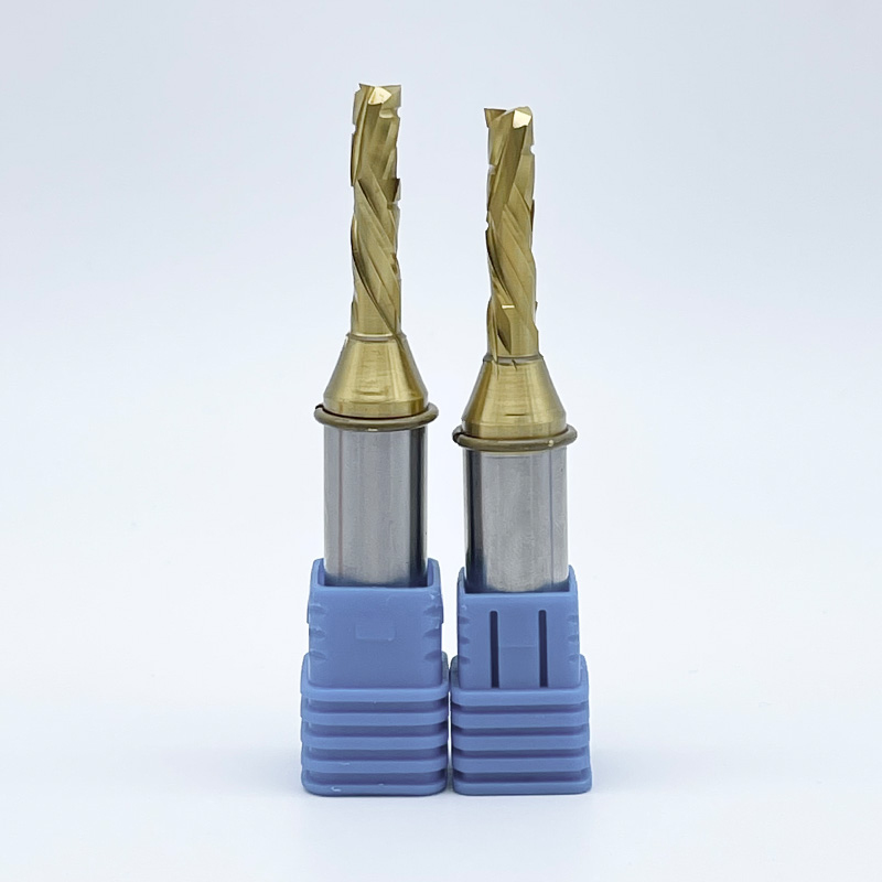
A routing end mill is a specialized cutting tool designed primarily for CNC gantry routers. These machines operate at exceptionally high spindle speeds, typically ranging from 10,000 to 24,000 RPM, and sometimes pushing up to 40,000 RPM on specialized equipment. At these velocities, the cutting dynamics change completely compared to traditional milling operations. The tool must evacuate material instantly to prevent heat buildup.
These tools feature distinct core characteristics engineered for rapid material removal in non-ferrous and non-metallic substrates. You will typically find lower flute counts, usually between one and three flutes. They utilize specialized flute geometries, such as the O-flute design, alongside specific upcut or downcut spiral configurations. The O-flute geometry creates a massive chip gullet, allowing the tool to curl and eject soft materials efficiently. These features provide enhanced chip clearance capabilities, preventing soft materials like acrylic or high-density polyethylene (HDPE) from melting or packing into the tool flutes during high-speed operation.
A standard end mill serves as the traditional milling cutter designed for Vertical Machining Centers (VMCs) and Horizontal Machining Centers (HMCs). These machines operate under high torque conditions at significantly lower RPMs, usually between 4,000 and 12,000 RPM. They rely on rigid cast-iron frames, box ways, or heavy-duty linear guides to push cutters through dense materials with immense force.
Standard end mills prioritize structural integrity above all else. They feature thicker core webs to withstand heavy radial loads without deflecting. You will see higher flute counts, ranging from four to six or more flutes, which help distribute cutting forces evenly across the tool and improve surface finishes in hard alloys. They utilize standard helix angles, typically between 30 and 45 degrees, and feature geometries optimized for shearing high-density ferrous metals rather than clearing massive volumes of lightweight chips.
Nomenclature overlap often causes confusion on the shop floor. You must differentiate solid carbide router end mills from traditional woodworking router bits. Solid carbide routing cutters are manufactured from a single piece of micro-grain carbide. They are designed for multi-axis CNC interpolation, continuous high-efficiency material removal, and precise dimensional accuracy. They are balanced for high-speed rotation and hold tight runout tolerances.
Conversely, traditional woodworking router bits usually feature brazed carbide tips welded to a steel body. They often include pilot bearings for manual edge profiling and operate at relatively lower efficiencies. While traditional bits work well for handheld routing or basic edge treatments in a woodshop, they lack the geometric complexity, balance, and solid carbide rigidity required for aggressive, continuous CNC production environments.
The fundamental divide between these tools lies in how they manage chip load. Routing cutters are dynamically balanced for high-velocity cutting. In a CNC router, chip load is managed by speed rather than torque. The tool relies on high RPMs to take thousands of tiny, rapid bites out of the material, shearing it away before heat can build up and transfer into the workpiece. If you calculate the feed rate (RPM × Flutes × Chip Load), a high RPM requires fewer flutes to keep the feed rate within the machine's physical limits.
Standard end mills require the rigid, high-torque environment of a traditional mill. A VMC uses torque to push the cutter through dense materials like 4140 steel or titanium. If you attempt to run a standard end mill at router speeds without sufficient torque, the tool will stall, chatter, or instantly snap. The cutting dynamics of standard mills depend on slow, forceful shearing action. The machine must have the mechanical advantage to drive the cutting edge through the metal matrix.
Flute density dictates a tool's ability to evacuate material. Routing cutters use fewer flutes to maximize the size of the chip gullet. When cutting plastics or aluminum at 18,000 RPM, the tool generates massive volumes of chips in milliseconds. A single-flute or two-flute design provides the necessary open space to eject these chips instantly. If chips remain in the cut zone, they generate friction. This friction causes plastics to melt and aluminum to weld directly to the cutting edge, a failure mode known as built-up edge (BUE).
Standard end mills use higher flute counts to distribute cutting forces and improve surface finish in hard metals. When machining steel, chip volume is lower, but the required cutting force is immense. A four-flute or six-flute end mill spreads this force across multiple cutting edges. This reduces individual tooth wear and prevents the cutter from snapping under heavy radial engagement. A higher flute count also allows for a faster feed rate at lower RPMs, optimizing the material removal rate in dense alloys.
Geometry in the routing world focuses heavily on the direction of chip flow. You must select the right spiral to match your material hold-down method and edge finish requirements. CNC routers often use vacuum tables, making upward lifting forces a major concern.
Standard end mill geometries focus on vibration control rather than directional chip flow. They utilize variable helix and variable pitch designs to break up harmonics and prevent chatter during rigid milling. By altering the spacing between the flutes and the angle of the helix, the tool prevents the machine from hitting a resonant frequency. This stabilizes the tool against the immense lateral forces generated when plowing through solid steel.
Structural differences in the tool's core diameter significantly impact performance. Standard end mills feature thicker cores to resist deflection under heavy radial loads. Because VMCs hold tight tolerances in dense metals, the tool cannot bend during the cut. A thicker core reduces the chip gullet size but provides the necessary backbone to survive heavy roughing passes.
When analyzing Length of Cut (LOC) and Overall Length (OAL), routing cutters are typically designed to be as short as possible for the application. Tool deflection increases to the third power of the length. Shorter tools are inherently more rigid. This built-in rigidity is critical for compensating for the lighter, less rigid frames of gantry routers compared to massive cast-iron VMCs. A shorter tool minimizes runout and deflection at high RPMs, ensuring dimensional accuracy even on a lighter machine.
Coatings dictate how a tool interacts with material at the microscopic level. Routing-specific finishes prioritize lubricity. A "Bright finish" means the solid carbide is uncoated but highly polished. This mirror-like surface enhances chip flow and prevents galling in softer, gummy materials like aluminum, wood, and plastic. Specialized coatings like Zirconium Nitride (ZrN) or Diamond-Like Carbon (DLC) are also used. These coatings maintain a low coefficient of friction, prevent material adhesion, and extend tool life in abrasive composites.
Standard end mill coatings are built for thermal endurance. You will frequently see Aluminum Titanium Nitride (AlTiN) or Titanium Aluminum Nitride (TiAlN) coatings. These coatings are designed to withstand extreme heat and oxidation when cutting ferrous metals. They actually rely on the heat of the cut to form a protective aluminum oxide layer. This thermal activation process requires temperatures exceeding 800°C, a threshold you will never reach when cutting wood or plastic. Using an AlTiN coated tool on plastic is counterproductive, as the coating adds microscopic roughness that causes plastic to stick and melt.
You should specify these high-speed cutters when processing large-format sheet goods and low-density materials. The geometry is specifically tuned for rapid evacuation and clean shearing of soft fibers or polymers. Primary use cases include:
Deploying the correct geometry ensures rapid chip evacuation. It prevents material melting in plastics, eliminates delamination in composite layups, and stops tear-out in wood veneers. The right tool allows you to maximize the feed rate capabilities of your gantry router.
Standard milling cutters belong in heavy metalworking applications. They are designed to survive the brutal environment of high-torque shearing. Primary use cases include:
Using these tools in their intended environment allows them to withstand high cutting temperatures. They maintain exceptional edge retention under heavy loads and provide reliable dimensional accuracy when hogging out dense materials. The thick core and specialized coatings ensure the tool survives the thermal and mechanical shock of metal cutting.
Aluminum represents the primary crossover zone where both tool types might be considered, requiring careful evaluation of trade-offs. If you are machining a solid 6061-T6 aluminum billet on a rigid VMC, a standard 3-flute aluminum-specific end mill is ideal. It provides the strength needed for heavy roughing passes and high radial engagement.
However, if you are profiling thin aluminum sheets on a high-speed gantry router, a single-flute routing cutter is vastly superior. The single flute provides the massive chip clearance needed at 18,000 RPM, preventing the aluminum from welding to the tool. The high spindle speed compensates for the lower feed per tooth, allowing you to maintain high linear feed rates without snapping the cutter.
Tool Selection and Machine Compatibility Summary
| Feature | Routing End Mills | Standard End Mills |
|---|---|---|
| Machine Architecture | CNC Gantry Routers, CNC Routers | VMCs, HMCs, Bed Mills |
| Operating RPM Range | High (10,000 - 24,000+) | Low to Medium (1,000 - 12,000) |
| Flute Count | Low (1 - 3 flutes) | High (3 - 6+ flutes) |
| Primary Materials | Wood, Plastics, Composites, Aluminum Sheet | Steel, Stainless, Titanium, Cast Iron |
| Chip Evacuation Strategy | Upcut, Downcut, Compression | Variable Helix, Variable Pitch |
| Core Thickness | Thin (Maximizes chip gullet) | Thick (Maximizes rigidity) |
| Optimal Coatings | Bright Finish, ZrN, DLC | AlTiN, TiAlN, TiCN |
Before selecting a tool, you must assess your machine's physical capabilities. Use this checklist to match the tool to the machine:
Frame your tooling decision around your specific production goals. If your priority is edge quality in sheet goods—such as preventing chip-out on melamine cabinets or achieving a glass-like finish on acrylic—you must favor specialized routing geometries. The right downcut or O-flute tool eliminates secondary finishing operations, saving hours of manual labor.
Conversely, if your goal is prioritizing volumetric removal in billet blocks, standard end mills win. When you need to turn a 50-pound block of steel into a 10-pound part as fast as possible, standard mills provide the structural integrity required for maximum MRR without catastrophic failure. You sacrifice some edge finish during roughing to achieve massive material removal.
Your workholding method dictates your tool geometry. CNC routers predominantly use vacuum tables. If you use an aggressive upcut router bit on a small, lightweight part, the lifting force of the tool will overpower the vacuum hold-down. The part will eject from the table, destroying the workpiece and potentially breaking the tool. In these scenarios, you must switch to a downcut tool to press the material into the spoilboard.
VMCs utilize mechanical vises, toe clamps, or heavy-duty fixtures. Because the workholding is mechanically rigid, standard end mills do not need to account for lifting forces. The programmer can focus entirely on optimizing the toolpath for chip thinning and radial engagement without worrying about the part moving.
Implementation Reality: Using a long-reach standard end mill on a less rigid CNC router causes severe chatter and eventual snap-offs. The machine frame flexes slightly under load, causing the tool to bite too aggressively, exceed its chip load, and break.
Mitigation: Calculate precise stick-out ratios. Only expose as much of the tool shank as absolutely necessary to clear the cut depth. Utilize shorter, specialized cutters to maximize rigidity and keep cutting forces as close to the spindle bearings as possible. Use a dial indicator to check runout before running the program.
Implementation Reality: Using a 4-flute standard end mill on polycarbonate plastic at 18,000 RPM will instantly melt the chips. The melted plastic welds directly to the tool flutes, turning the cutter into a blunt, glowing-hot friction rod that ruins the part and poses a fire hazard.
Mitigation: Switch to a single O-flute tool with a bright finish. Adjust your feed rates to ensure chips are sheared cleanly and ejected immediately. A heavier chip load actually pulls heat away from the cut zone and into the chip. Never let the tool dwell in plastic.
Implementation Reality: Running heavy, unbalanced standard end mills at extreme router speeds can destroy expensive spindle bearings. Standard tools are not always balanced for 24,000 RPM operation, leading to micro-vibrations that tear apart ceramic bearings over time.
Mitigation: Ensure all tools are dynamically rated and balanced for the specific RPM range of your machine. Stick to tools explicitly manufactured for high-speed routing environments to protect your spindle investment. Regularly clean your collets and tool holders to prevent dust buildup from throwing off the balance.
Take the following actionable steps to optimize your machining processes and protect your equipment:
A: Yes, but only for certain materials like aluminum, and only if feed rates and RPMs are strictly calculated. You must avoid burning the tool or melting the material due to high flute counts. Generally, it is not recommended for wood or plastics.
A: No. Router bits typically refer to woodworking tools with brazed carbide tips and bearings, while routing end mills are solid carbide industrial cutting tools designed for multi-axis CNC interpolation and high-speed production.
A: Upcut pulls chips upward, making it ideal for slotting and clearing debris, but it can fray top edges. Downcut pushes chips downward, leaving a clean top edge but requiring alternative chip clearance strategies to prevent packing in the cut channel.
A: They operate at very high RPMs in softer materials. Fewer flutes create larger chip gullets, allowing the massive volume of chips generated at high speeds to evacuate quickly without packing, rubbing, or melting the material.
A: It is highly discouraged. Router end mills lack the core thickness, edge geometry, and heat-resistant coatings required to shear dense ferrous metals. Attempting to cut steel will likely result in immediate tool breakage and potential spindle damage.
A: A compression tool combines an upcut geometry at the tip with a downcut geometry on the upper portion of the flute. This pulls the material toward the center of the cut, leaving perfectly clean, tear-free edges on both the top and bottom of laminated materials.