- All
- Product Name
- Product Keyword
- Product Model
- Product Summary
- Product Description
- Multi Field Search

Views: 0 Author: Site Editor Publish Time: 2026-08-04 Origin: Site

While square end mills are the foundational rotary cutting tools of modern CNC machining, defaulting to them without analyzing part geometry and toolpath strategy often leads to premature tool failure and compromised surface finishes. Walk onto any shop floor, and you will see these tools loaded into almost every machine magazine. However, machinists and tooling buyers must balance the strict print requirement for crisp 90-degree corners and flat bottoms against the inherent fragility of sharp tool corners under high cutting forces and thermal loads. Pushing a sharp corner too hard in tough alloys guarantees chipped flutes and scrapped parts. This guide breaks down the specific applications of square end mills, evaluates the critical trade-offs between flat and radiused geometries, and provides a technical framework for selecting the right cutter for your material and toolpath.
Understanding the physical anatomy of the cutter dictates how it behaves under load inside the spindle. The geometry directly influences cutting forces, heat generation, and the resulting surface finish on the workpiece. You cannot push a tool past its mechanical limits, and knowing those limits starts with the grind.
The defining characteristic of this tool is its flat bottom intersecting with the peripheral cutting edges at a sharp 90-degree angle. This geometry generates specific cutting forces during operation. When engaged in side milling, the tool experiences high radial forces that push the cutter away from the workpiece. During plunging or heavy axial cuts, forces push straight up into the machine spindle.
Most flat-bottomed tools actually feature a microscopic dish angle—typically between 1 and 2 degrees—on the bottom cutting edges. A perfectly flat bottom would drag across the freshly cut floor. This dragging action creates massive friction, generates excessive heat, and causes work hardening in materials like 304 stainless steel. The slight concavity ensures only the outer cutting edges engage the material, leaving a clean surface finish without rubbing.
The interface between the tool shank and the tool holder determines the overall rigidity of the cutting assembly. You have two primary shank styles on the shop floor, and they dictate your runout.
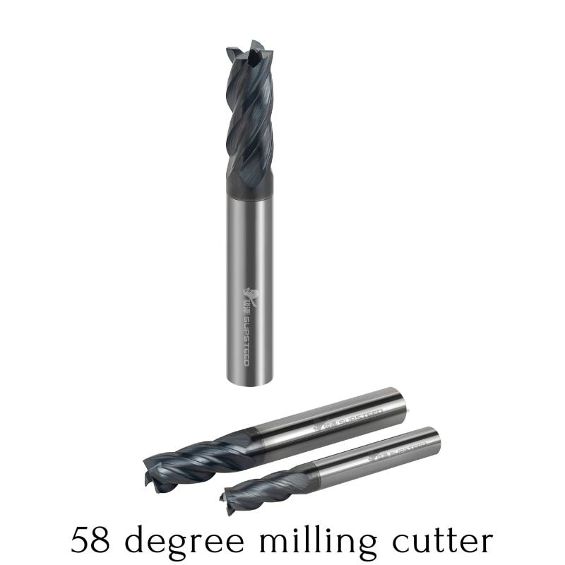
Industry terminology often causes confusion during tooling procurement and CAM programming. The terms flat end mills and square end mills are exact synonyms. Tooling manufacturers, machinists, and software platforms use these terms interchangeably to describe the same 90-degree corner geometry. Neither term implies a difference in cutting mechanics, flute design, or material capability. If a print calls for a flat bottom, you pull a square tool.
A successful machining operation utilizing this specific geometry achieves strict dimensional accuracy on perpendicular walls and flat floors in a single setup. The primary goal is to eliminate the need for secondary finishing operations. Success means the tool leaves a crisp 90-degree internal corner without exhibiting chatter marks on the walls, cusp marks on the floor, or taper caused by tool deflection. If you have to go back in with a file or a secondary finishing pass to clean up chatter, the initial operation failed.
These cutters handle specific geometric features that radiused or ball-nose tools simply cannot generate. Their application is dictated by the mechanical requirements of the final part. You use them when the print leaves you no other choice.
Creating flat-bottomed features requires a tool that cuts cleanly across its entire diameter. The flat geometry generates a smooth, perpendicular floor necessary for mating parts, bearing pockets, or hardware clearances.
Full-width slotting is the most punishing operation for any milling cutter because the tool experiences 180 degrees of radial engagement. This traps chips within the cut zone. As the tool advances, it continuously recuts its own chips. Recutting chips destroys the sharp corners of the tool instantly due to rapid heat spikes and mechanical impact. Deep pocketing presents similar chip evacuation challenges. Machinists must program optimal step-overs and utilize high-pressure coolant or strong air blasts to flush chips out of the pocket before the flutes re-engage the material.
Peripheral cutting uses the side flutes to generate straight, perpendicular walls along the outside contour of a part. Side milling typically utilizes a smaller radial depth of cut but leverages the full axial length of cut (LOC).
When profiling deep walls, the core diameter of the tool becomes the critical factor. A thicker core provides the necessary rigidity to resist bending forces. If the tool lacks rigidity, the cutting forces will push it away from the workpiece, leaving a tapered wall that fails dimensional inspection. Climb milling is the preferred technique for profiling. It generates a thick-to-thin chip, pulling the heat away from the part and leaving a superior surface finish. Conventional milling rubs the material before cutting, which will quickly dull a sharp 90-degree corner.
While large surface areas require dedicated shell mills or face mills, smaller parts often rely on standard end mills for facing operations. A dedicated face mill might be too large to clear workholding clamps, fixture walls, or adjacent part features. A smaller diameter flat cutter provides the necessary clearance to face off a boss or level a small surface. Because the tool has a sharp corner, machinists must carefully overlap their step-overs—typically 50% to 70% of the tool diameter—to ensure a perfectly flat surface without leaving ridges between passes.
Direct Z-axis plunging requires specific tool geometry. You cannot just drive any flat tool straight down into a block of steel.
The decision between a sharp corner and a radiused corner dictates the maximum material removal rate and the overall lifespan of the cutter. Understanding the physics of the tool corner is essential for optimizing production runs and keeping tooling costs under control.
The physics of a sharp 90-degree corner make it inherently fragile. The sharp point acts as a mechanical stress riser, focusing all cutting forces into a microscopic area. When machining harder materials like 4140 steel, titanium, or nickel-based superalloys, this sharp corner also becomes a focal point for extreme thermal concentration.
The heat cannot dissipate fast enough through the thin carbide matrix at the tip. This leads to rapid thermal shock, micro-fracturing, and eventual corner chipping. Once the corner chips, the tool leaves a poor surface finish and the risk of catastrophic tool failure increases exponentially. Corner radius end mills solve this problem by distributing heat and cutting forces over a significantly larger surface area. The radius eliminates the weak point, preventing thermal shock and allowing the tool to absorb much higher impact forces during heavy radial engagement.
Modern CAM software utilizes dynamic milling toolpaths to maintain a constant chip load and prevent sudden spikes in tool engagement. These toolpaths rely on radial chip thinning, allowing machinists to run much higher feed rates. CAM programmers almost exclusively prefer corner radius tools for these dynamic roughing operations. The radiused corner withstands the aggressive feed rates and high spindle speeds without fracturing.
The standard decision framework for modern CNC programming follows a strict rule: rough the part with a corner radius tool to maximize material removal rates and protect tool life. Only introduce the sharp-cornered tool during the final finishing pass, and only if the part print strictly dictates a sharp 90-degree internal corner. If the engineering drawing permits a small internal radius, the sharp tool should be eliminated from the process entirely.
Tool Geometry Performance Comparison
| Performance Metric | Square End Mill | Corner Radius End Mill |
|---|---|---|
| Corner Strength | Low (Prone to chipping) | High (Impact resistant) |
| Thermal Dissipation | Poor (Heat concentrates at tip) | Excellent (Heat spreads over radius) |
| Max Feed Rate (Roughing) | Moderate | Very High |
| Bottom Finish Capability | True 90-degree flat bottom | Leaves a radiused fillet |
| Ideal Application | Finishing walls and floors | Dynamic roughing and heavy profiling |
Tool selection requires matching the cutter's physical properties to the material being machined. Incorrect flute counts or coatings will cause immediate process failure. You cannot run an aluminum-specific tool in stainless steel and expect it to survive.
The number of flutes dictates the size of the chip valley and the core strength of the tool.
Coatings protect the raw carbide substrate from heat and abrasive wear. Selecting the right coating depends entirely on the material and the coolant strategy.
Standard cutting tools feature symmetrical flutes with equal spacing. As these equal cutting edges strike the material at a constant frequency, they generate harmonic resonance. This vibration causes chatter, leaving terrible surface finishes and destroying the sharp corners of the tool.
Variable pitch and variable helix designs solve this problem. By altering the spacing between the cutting edges (e.g., 88 degrees, 92 degrees, 89 degrees, 91 degrees) and changing the helix angle along the length of the flute, the tool breaks up the harmonic frequency. The irregular impacts prevent resonance from building up. This allows machinists to push heavier depths of cut, run faster feed rates, and achieve mirror-like surface finishes without chatter.
Tool Selection Matrix
| Workpiece Material | Recommended Flute Count | Ideal Coating | Coolant Strategy |
|---|---|---|---|
| Aluminum / Non-Ferrous | 2 or 3 Flutes | ZrN or Uncoated Polished | Flood Coolant |
| Carbon / Alloy Steel | 4 or 5 Flutes | TiAlN or AlTiN | Air Blast or Flood Coolant |
| Stainless Steel | 4, 5, or 6 Flutes | AlTiN or TiCN | High-Pressure Coolant |
| Titanium / Superalloys | 5, 6, or 7+ Flutes | AlTiN (High Aluminum content) | High-Pressure Coolant |
| Plastics / Composites | 1 or 2 Flutes | Uncoated Polished | Air Blast or Dry |
Even the highest quality carbide tools will fail if implemented poorly. Machinists must actively manage physical risks through programming and setup techniques. You control the environment the tool operates in.
Tool deflection occurs when radial cutting forces push the cutter away from the workpiece. Because the tool is secured at the spindle and free at the bottom, it bends like a diving board. This bending leaves tapered walls rather than true 90-degree profiles. Deflection increases exponentially with tool length. If you double the stick-out of the tool, deflection increases by a factor of eight.
To mitigate deflection, always use the shortest possible length of cut (LOC) and overall length (OAL) that the part geometry allows. Maximize the shank diameter for added rigidity. When dimensional accuracy is critical, program a spring pass. A spring pass is a secondary finishing pass run at the exact same coordinates as the previous pass. Because the tool is removing almost zero material, cutting forces drop to zero, allowing the tool to spring back to its true vertical position and clean up the taper.
The sharp corners of the tool are highly susceptible to instantaneous chipping upon entry or during heavy radial engagement. Plunging straight down into hard metal spikes the cutting forces and shatters the corners immediately.
Mitigate this risk by implementing arc-in or helical entry toolpaths. Ramping down into the material gradually reduces the initial shock on the cutting edges. Furthermore, CAM programmers must reduce feed rates specifically in the internal corners of a pocket. When a tool drives into a 90-degree corner, the radial engagement spikes drastically. Slowing down the feed rate in these specific zones prevents the tool from snapping under the sudden load.
Micro-vibrations and runout destroy sharp corners. Transitioning tooling strategies from manual milling machines to high-speed CNCs often exposes a lack of machine rigidity or poor tool holding. A loose setup causes the tool to bounce in the cut, fracturing the 90-degree edge.
Utilize high-precision holders to minimize runout. When runout is minimized, the chip load is distributed perfectly evenly across all cutting edges. Ensure the workpiece is clamped rigidly to the table. Any vibration in the fixture will transfer directly into the fragile corners of the cutter.
These cutters remain indispensable for finishing flat bottoms and sharp shoulders in precision manufacturing. However, their fragile 90-degree corners make them suboptimal for heavy roughing in hard materials compared to radiused alternatives. Success on the shop floor requires treating these tools as specialized finishing instruments rather than blunt-force roughers. Base your tooling selection strictly on the part print. If a 90-degree corner is explicitly required, specify a flat cutter for the final finishing pass. Select your flute count based on the material's chip-forming characteristics, and prioritize variable geometry and rigid tool holding for deep or aggressive cuts.
A: Yes, provided the tool features a center-cutting geometry. Center-cutting tools have cutting edges that extend to the center of the tool axis, allowing direct Z-axis plunging. If the tool is non-center-cutting, it leaves a core of material and will crash if plunged directly. For non-center-cutting tools, ramping or helical interpolation is required to enter the cut.
A: There is no difference. These two terms describe the exact same tool geometry. Both refer to a milling cutter with a flat bottom and sharp 90-degree corners designed to cut perpendicular walls and flat floors. Tooling manufacturers, software platforms, and machinists use the terms interchangeably on the shop floor.
A: Corner chipping usually results from excessive feed rates, lack of setup rigidity, or excessive tool runout. Thermal shock from applying flood coolant during hard milling also causes micro-fractures in the carbide. Additionally, using a sharp-cornered tool for heavy roughing instead of a corner radius tool will lead to rapid corner failure.
A: No, they are not recommended for 3D contouring. The sharp 90-degree corners will dig into the material and leave distinct, stair-stepped cusp marks on complex curved surfaces. Ball nose end mills are required for 3D profiling because their rounded profile generates smooth, continuous surface finishes across changing topographies.
A: You should use 4 to 6 flutes when cutting steel. A higher flute count provides a larger core diameter, which increases the tool's overall strength and rigidity. This manages the higher cutting forces, distributes heat more effectively across multiple cutting edges, and allows for appropriate feed rates in harder ferrous materials.