- All
- Product Name
- Product Keyword
- Product Model
- Product Summary
- Product Description
- Multi Field Search

Views: 0 Author: Site Editor Publish Time: 2026-08-08 Origin: Site
Machinists face a constant battle when programming complex internal features. Overhangs, deep cavities, and backside geometries usually force you to pull the part out of the vise and set it up again. Standard end mills simply cannot reach these hidden profiles without the shank colliding with the workpiece. Relying on standard square or ball end mills for complex contours forces operators into multiple fixture changes. This approach kills cycle times, drives up labor requirements, and introduces severe tolerance stacking risks. Every time you unclamp a part, you lose precision. Modern manufacturing demands single-setup execution to maintain tight tolerances and keep the spindle running. Integrating undercutting end mills enables single-setup machining for backside features, complex contours, and hard-to-reach channels. These tools eliminate the need to flip parts, directly reducing scrap rates and optimizing your production workflow.
Moving a part between fixtures to reach underside edges introduces massive operational risks. When you machine a bore in operation one, and then flip the part to chamfer the backside in operation two, you rely entirely on the accuracy of your vise stop, the flatness of your parallels, and the repeatability of your probing cycle. If your vise jaw lifts even slightly, or your probe cycle has a tiny margin of error, you are already stacking deviations. By the time the tool touches the metal, that backside chamfer might be visibly off-center. For aerospace components with tight true position tolerances, this multi-setup approach guarantees a high scrap rate. Operators spend valuable hours dialing in fixtures instead of making chips, which destroys shop floor efficiency.
Every setup change creates micro-deviations in part alignment. A part requiring three separate setups to machine internal channels and backside chamfers carries three times the alignment risk of a single-setup operation. You also have to account for the thermal expansion of the machine and the part between setups. If a part sits on a bench overnight before operation two, the material dimensions change. Single-setup machining eliminates these variables, but it requires tooling capable of reaching every feature without interference.
Standard square or ball end mills have strict physical constraints. Their shanks are typically the exact same diameter as, or larger than, their cutting edges. When encountering overhanging features or deep internal cavities, the tool shank collides with the workpiece long before the cutting edge can reach the target surface. Backside edge access becomes geometrically impossible. You cannot cut an undercut profile using a tool that lacks neck relief. The rigid, straight design of conventional end mills restricts them to line-of-sight machining from the spindle's perspective.
Consider a scenario where you need to cut a wide O-ring groove inside a narrow bore. A standard end mill small enough to enter the bore will not have the radial reach to cut the groove depth. If you use a larger tool to get the radial reach, it won't fit through the bore opening. This geometric trap forces machinists to either split the part into two pieces or use specialized tooling designed specifically for clearance.
Failing to reach complex geometries in the primary machine setup forces secondary operations. Manual deburring, secondary CNC routing, or specialized broaching add massive hidden costs to every production run. These secondary steps consume lost machine capacity and increase overall scrap rates. Human error during manual finishing often damages expensive parts right at the end of the manufacturing cycle. An operator slipping with a hand deburring tool can scrap a part that already has hours of machine time invested in it.
Extended lead times result directly from waiting for secondary workstations to become available. If your CNC mill finishes a batch of parts, but they have to sit in a queue for manual backside chamfering, your floor-to-door time skyrockets. Eliminating these extra steps by finishing the part completely in the mill is the only way to maintain a competitive edge in modern machining.
An undercutting end mill features a highly specialized structural design engineered specifically for clearance. The tool consists of three main sections: the cutting head, the relieved neck, and the shank. The cutting head contains the flutes and performs the actual material removal. Immediately behind the head, the neck diameter is significantly reduced. This relieved neck provides the necessary clearance to reach past overhangs without rubbing against the workpiece. The shank remains at a standard diameter to ensure secure clamping in the toolholder.
The transition between the cutting head and the relieved neck is a critical design feature. High-quality tools utilize a smooth, blended radius at this junction to prevent stress risers. A sharp corner at the neck transition creates a weak point where the tool will inevitably snap under cutting pressure. This unique geometry shifts the cutting action away from the tool's centerline axis, allowing it to reach areas standard tools cannot.
Wrap angle defines the degree of the spherical cutting edge on the tool head. A standard ball end mill has a 180-degree wrap angle, meaning it cuts only on the bottom half of the sphere. Undercutting tools feature wrap angles exceeding 180 degrees, often reaching 220 to 300 degrees. Increased wrap angles allow the tool to cut upward and sideways. This expanded cutting coverage provides greater versatility and clearance in multi-axis contouring.
When programming a 5-axis toolpath, the tool axis constantly tilts relative to the part surface. A high wrap angle ensures that the cutting flutes remain engaged with the material regardless of the approach angle. If you try to tilt a standard ball end mill too far, the non-cutting shank will drag across the part. The extended wrap angle is the defining feature that makes complex undercutting possible.
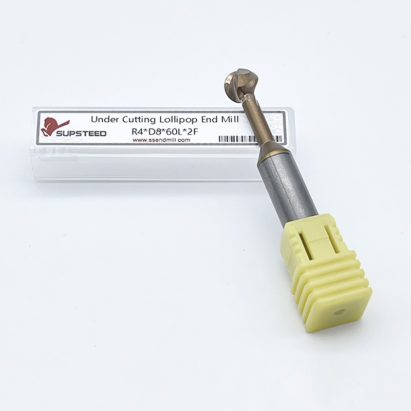
Terminology in the machining industry often overlaps, causing confusion during tool selection. While many machinists use the terms interchangeably, distinct differences exist. Lollipop cutters specifically refer to spherical ball end mills featuring extremely high wrap angles, typically between 270 and 300 degrees. Their fully spherical heads resemble a lollipop on a stick. They are primarily used for complex 3D profiling and 5-axis contouring where the tool approach angle changes drastically.
Undercutting end mills represent a broader category. They include lollipop styles but also encompass tools with flat bottoms, corner radiuses, and specific angled profiles designed for targeted undercut features. For example, a tool designed to cut a 45-degree backside chamfer is an undercutting end mill, but it is not a lollipop cutter because it lacks a spherical head. Understanding this distinction helps you select the exact tool geometry required for your specific part feature.
The undercutting family includes several specific profile shapes tailored for distinct applications. Cherry ball cutters feature a spherical head optimized for milling smooth fluid channels and rounded internal cavities. They are often used in mold making to machine deep, contoured pockets. Dovetail cutters utilize an angled, inverted cone shape to machine angled undercuts and specialized workholding features. You will frequently use dovetail cutters to prep raw stock for 5-axis self-centering vises.
Keyseat and T-slot cutters feature a wide, flat cutting head on a narrow neck, designed specifically for targeted internal grooving and slotting operations. These are essential for cutting retaining ring grooves inside bores. Selecting the correct profile depends entirely on the required geometry of the finished part. You must match the tool's cutting profile exactly to the print specifications to avoid gouging the workpiece.
One of the most frequent applications involves reaching through a bore or past an edge to chamfer the underside of a part. Standard tools require the operator to flip the workpiece to access these bottom edges. Undercutting tools drop through the hole, shift laterally, and pull upward to break the edge. This technique eliminates manual finishing and saves significant downtime. You can program a simple circular interpolation toolpath to perfectly chamfer the backside of a drilled hole in seconds.
Automated backside deburring ensures consistent edge breaks across entire production runs, removing the variability inherent in manual hand-tool operations. When you have a part with fifty cross-drilled holes, manually deburring the internal intersections takes hours. An undercutting tool can reach inside the main bore and deburr every intersecting hole automatically, guaranteeing a burr-free part straight off the machine.
Manifold manufacturing and hydraulic component production require complex internal routing. Fluid flow channels must be milled with high surface finish requirements to prevent turbulence and pressure drops. Undercutting profiles excel at interpolating smooth, continuous O-ring grooves inside deep bores. The relieved neck allows the cutting head to reach deep into the valve body and machine the groove without the shank contacting the bore walls.
This capability is essential for creating reliable, leak-free hydraulic assemblies. When machining an internal O-ring groove, the surface finish of the groove floor and walls dictates the seal's integrity. A specialized undercutting tool with the correct corner radius can plunge into the bore, feed radially into the wall, and sweep the groove in a single pass, leaving a pristine surface finish that guarantees a perfect seal.
Many shops assume complex undercuts require expensive 5-axis machinery. However, undercutting tools can be utilized effectively in standard 3-axis CNC machines. By programming the tool to drop below an overhang and interpolate outward, machinists can cut backside features without requiring a 5-axis trunnion or rotary table. This strategy maximizes the capability of existing 3-axis equipment.
It allows shops to take on more complex work without investing in new machine tools, directly improving shop floor profitability. You can machine complex T-slots, internal keyways, and backside counterbores using standard 3-axis toolpaths. The key is ensuring your CAM software accurately simulates the tool's neck and shank to prevent collisions during the lateral cutting moves.
Aerospace and medical manufacturing rely heavily on continuous multi-axis toolpaths. Components like turbine impellers and orthopedic bone plates feature complex, sweeping organic shapes. Lollipop profiles are critical here. The spherical cutting edge maintains constant material engagement as the 5-axis machine tilts and rotates the part. The high wrap angle ensures the tool continues cutting smoothly even as the approach vector changes drastically.
This continuous engagement prevents dwell marks and delivers superior surface finishes on complex 3D contours. When machining an impeller blade, the tool must reach deep between the blades while the machine head tilts to avoid the adjacent blade. Only a tool with a massive wrap angle and a heavily relieved neck can navigate this tight geometry without causing a catastrophic collision.
Creating retaining ring grooves inside pre-drilled holes requires specialized internal access. Specific undercutting profiles, such as T-slot cutters, are deployed to machine these features. The tool enters the existing cavity, feeds radially into the wall to the required depth, and interpolates a full circle to create the groove. This method is highly efficient for cutting internal keyways, snap-ring grooves, and custom retaining slots inside deep pockets where standard slitting saws cannot reach.
You must carefully control the chip load during these internal grooving operations. Because the tool is cutting inside a confined space, chip evacuation is difficult. Taking multiple light radial passes rather than one heavy plunge cut helps break the chips and prevents them from packing into the flutes, which would otherwise snap the fragile neck of the tool.
Matching the tool's wrap angle to the specific undercut angle of the part ensures adequate clearance. A decision framework starts with analyzing the part print. If the undercut requires a 45-degree upward cut, the tool must have a wrap angle that exceeds 180 degrees by at least 45 degrees on each side. This means you need a minimum 270-degree wrap angle. Selecting a tool with insufficient wrap angle causes the non-cutting neck to rub against the workpiece.
This rubbing generates massive friction, resulting in catastrophic tool failure, work hardening of the material, and scrapped parts. Always choose a wrap angle slightly larger than the maximum required cutting angle to provide a safety margin. When programming in CAM, verify the contact point of the tool against the surface model to ensure the flutes are doing the work, not the neck.
The most critical trade-off in tool selection is balancing reach against rigidity. Longer, thinner necks provide greater reach into deep cavities. However, they exponentially increase the risk of deflection and chatter. A neck that is too long acts like a tuning fork, vibrating violently under cutting forces. This harmonic vibration destroys surface finish and chips the carbide cutting edges.
Machinists must select the absolute shortest possible neck length that still clears the part geometry. If a deep reach is unavoidable, the neck diameter must be maximized to retain as much core strength as possible without causing interference. A neck that is just 0.010 inches thicker can increase the tool's rigidity significantly, allowing you to maintain productive feed rates without inducing chatter.
Flute count directly impacts chip evacuation and surface finish. The material being machined dictates the optimal number of flutes. You cannot use the same tool for aluminum and titanium and expect good results.
The thermal dynamics of machining deep undercuts demand specific carbide grades and coatings. Deep cavities trap heat because coolant struggles to reach the cutting zone. Premium micro-grain carbide substrates resist the bending forces applied to the relieved neck, providing high transverse rupture strength. Coatings like Titanium Aluminum Nitride (TiAlN) and Aluminum Titanium Nitride (AlTiN) provide exceptional thermal barriers.
These coatings oxidize at high temperatures, forming a protective ceramic layer that extends tool life in hard alloys. They thrive in high-heat environments where uncoated carbide would break down instantly. For aluminum and plastics, uncoated or Zirconium Nitride (ZrN) coated tools prevent built-up edge. ZrN provides a slick surface that stops gummy aluminum from welding to the cutting flutes, keeping the edges razor-sharp.
The relieved neck design makes these tools highly susceptible to runout. Even minimal runout at the spindle amplifies at the cutting tip due to the extended reach. Standard ER collet chucks often lack the necessary gripping force and concentricity for extended-reach undercutting. If a tool has 0.0005 inches of runout at the collet face, that can translate to 0.003 inches of runout at the tip of a long neck.
High-precision toolholders, such as shrink fit or hydraulic chucks, are highly recommended. These holders provide 360-degree clamping pressure, maximizing rigidity and dampening vibration. Controlling runout extends tool life, improves surface finish, and prevents the fragile neck from snapping under uneven chip loads. When one flute takes a heavier chip than the others due to runout, the tool deflects and breaks.
Tool Selection Matrix
| Workpiece Material | Recommended Flute Count | Optimal Coating | Primary Consideration |
|---|---|---|---|
| Aluminum / Non-Ferrous | 2 to 3 Flutes | Uncoated or ZrN | Maximize chip evacuation space to prevent packing. |
| Plastics / Composites | 2 Flutes | Uncoated | Maintain razor-sharp edges to prevent melting. |
| Stainless Steel | 4 to 5 Flutes | AlTiN or TiAlN | Balance core rigidity with moderate chip clearance. |
| Titanium / High-Temp Alloys | 5+ Flutes | AlTiN | Maximize core diameter to prevent deflection and chatter. |
Financial justification requires looking beyond the initial purchase price. Undercutting end mills carry a higher initial cost than standard end mills due to their complex grinding requirements and specialized geometry. However, the return on investment is realized rapidly on the shop floor. The ROI comes directly through the elimination of secondary setups, reduced machine downtime, and the eradication of manual deburring labor.
Saving twenty minutes of setup time per part easily pays for the premium tool cost within the first production shift. Faster floor-to-door times increase overall shop profitability. When you stop pulling parts out of the machine to flip them, your spindle uptime increases. You are trading a slightly higher consumable tooling cost for a massive reduction in labor hours and machine idle time.
Integrating specialized cutting tools maximizes the output of expensive CNC machinery. A 5-axis mill sitting idle while an operator flips a part is wasting capital. Utilizing tools designed for complex contours allows continuous, uninterrupted toolpaths. This enables true single-setup manufacturing. By keeping the spindle turning and the machine cutting, shops extract the maximum value from their equipment investments.
Complex parts can be machined complete in one operation, drastically improving throughput. This capability allows the shop to take on more complex, higher-margin contracts that competitors cannot quote because they lack the tooling strategy to machine the parts efficiently. Maximizing machine capability is about matching advanced kinematics with the right cutting geometry.
The lack of rigidity in the relieved neck presents a significant engineering challenge. Deflection occurs when cutting forces push the tool away from the programmed path. Chatter is the harmonic vibration resulting from this deflection. To compensate, machinists must use lighter radial step-overs. Reducing the radial depth of cut (RDOC) lowers the pressure on the tool. You might need to drop your RDOC to just 5% of the tool diameter to maintain stability.
Feed rates should be adjusted to maintain a consistent chip load without overloading the neck. Utilizing CAM software to program arcing lead-ins and lead-outs prevents sudden spikes in tool pressure during entry and exit. Never plunge an undercutting tool straight into the material. Always ramp or helix into the cut to gradually build cutting pressure and prevent the neck from snapping.
Troubleshooting Chatter in Undercutting Operations
| Symptom | Probable Cause | Corrective Action |
|---|---|---|
| High-pitched squealing | RPM too high for the neck length | Reduce spindle speed by 20% to change the harmonic frequency. |
| Poor surface finish on walls | Tool deflection pushing away from cut | Program a spring pass (zero stock removal pass) to clean up the wall. |
| Tool snapping at the neck transition | Excessive radial engagement or runout | Reduce radial step-over and verify toolholder concentricity. |
| Chips welding to the flutes | Inadequate coolant or wrong coating | Increase coolant pressure or switch to a ZrN coated/uncoated tool. |
Maintaining a constant chip load is critical for tool survival. Machining undercuts often involves varying engagement angles. Toolpath strategy dictates success. Climb milling is generally preferred for surface finish, but in undercutting scenarios, it can pull the fragile tool into the workpiece, causing catastrophic failure. The cutting forces in climb milling grab the material and pull the tool forward.
Conventional milling is often safer for heavy undercuts because it pushes the tool away from the part, maintaining predictable deflection. Programmers must carefully analyze the cutting forces and adjust feed rates dynamically as the tool navigates tight internal corners. When the tool enters a corner, the radial engagement spikes. Your CAM software must be set to automatically reduce the feed rate in corners to prevent tool breakage.
Clearing chips from inverted or blind undercuts is notoriously difficult. Gravity works against the operation, trapping chips inside the cavity. Recutting these trapped chips destroys the cutting edges instantly. Flood coolant often fails to penetrate deep undercuts because the tool head blocks the fluid from reaching the cutting zone. The heat builds up rapidly, leading to thermal cracking of the carbide.
High-pressure coolant systems or targeted air blasts are required to blast chips out of the cutting zone. Through-coolant tool designs offer the best solution, delivering high-pressure fluid directly to the cutting edge. This flushes chips outward and provides critical lubrication to the cutting zone. If machining cast iron or hardened steel, use a high-pressure air blast instead of coolant to avoid thermal shock to the carbide.
Accurate CAM simulation is an absolute necessity. Programming undercuts blindly is a guaranteed way to crash a machine. The risks of shank collisions with overhanging part features are exceptionally high. Programmers must utilize advanced toolpath verification software. The digital twin must include accurate models of the tool, the relieved neck, the shank, and the toolholder.
Running full kinematic simulations ensures safe neck clearances throughout the entire toolpath. Any gouge or collision detected in the software must be resolved by adjusting approach angles or selecting a tool with greater reach. You must define the non-cutting portions of the tool accurately in your tool library. If the CAM software thinks the entire tool is a cutting flute, it will drive the shank straight through your workpiece.
A: An undercutting end mill is a broad category of tools featuring a relieved neck for clearance. A lollipop cutter is a specific type of undercutting tool featuring a fully spherical cutting head with a very high wrap angle, typically between 270 and 300 degrees, resembling a lollipop on a stick.
A: Programming requires defining the exact tool geometry, including neck diameter and length. You must use specialized undercut or 3D contouring toolpaths. You must run full collision simulations to ensure the non-cutting shank and neck do not interfere with overhanging part features during the cut.
A: The maximum wrap angle for most standard lollipop cutters is typically around 300 degrees. The remaining 60 degrees is occupied by the physical connection to the relieved neck. This high angle allows for extreme multi-axis contouring and upward cutting motions without shank interference.
A: Yes. In 3-axis machines, they are highly effective for machining backside chamfers, T-slots, and O-ring grooves. The tool drops below the overhanging feature and interpolates laterally in the X and Y axes, eliminating the need for a 5-axis rotary table or secondary setups.
A: Prevent breakage by minimizing neck length to maximize rigidity. Use high-precision toolholders like shrink fit to eliminate runout. Program lighter radial step-overs, maintain a constant chip load, and consider conventional milling to prevent the tool from pulling aggressively into the workpiece.
A: They can machine almost any material if the correct geometry is selected. Use 2-3 flute uncoated tools for aluminum and plastics to prevent chip packing. Use 4+ flute tools with advanced coatings like AlTiN for stainless steel, titanium, and high-temperature aerospace alloys.
A: Analyze the part's cross-section in your CAD software. Measure the maximum depth of the undercut and the height of the overhang. Select a tool where the neck length exceeds the overhang height and the neck diameter is smaller than the narrowest entry point.