- All
- Product Name
- Product Keyword
- Product Model
- Product Summary
- Product Description
- Multi Field Search

Views: 0 Author: Site Editor Publish Time: 2026-08-17 Origin: Site

Selecting the right end mill dictates whether you produce a clean part or snap a tool. Poor chip evacuation causes recutting, excessive heat generation, and tool deflection. This ruins parts and breaks tooling. Desktop and hobby-grade CNC routers struggle here because they lack the rigidity and torque to push multi-flute cutters through dense materials. You need a solution that matches your machine's actual capabilities.
Understanding the mechanics of single flute upcut end mills solves this problem. These tools provide aggressive chip-clearing capabilities and require lower feed rates. They also offer a wider margin of error for beginners learning feeds and speeds. By matching the tooling to your machine’s limits, you manage thermal thresholds effectively and keep your spindle running smoothly.
Chip load represents the physical thickness of the material removed by a single cutting edge during one full revolution. Maintaining the correct chip load keeps your tool alive. When carbide shears through metal or plastic, the friction generates intense heat. A proper chip load forces that heat into the ejected chip. If your chip is too thin, the cutting edge rubs against the stock instead of biting into it. Rubbing creates massive heat buildup, dulls the carbide, and ruins the workpiece.
The math behind chip load dictates why single flute tools dominate lightweight machines. The formula is simple: Feed Rate = RPM × Number of Flutes × Target Chip Load. Consider a standard hobby router spinning at 24,000 RPM. If you want a conservative 0.002-inch chip load in aluminum using a 4-flute end mill, you must feed the machine at 192 inches per minute (IPM). Most desktop CNCs lack the stepper motor torque and frame rigidity to push through aluminum at 192 IPM without losing steps or chattering violently.
Switching to a single flute cutter changes the math entirely. To hit that exact same 0.002-inch chip load at 24,000 RPM, you only need a feed rate of 48 IPM. This speed sits comfortably within the operational limits of almost every entry-level CNC machine on the market.
The physical architecture of single flute router bits also features a massive gullet. The gullet is the open void between the cutting edge and the core of the bit. With only one flute taking up space, the gullet occupies nearly half the tool's diameter. This open geometry scoops up large, thick chips and throws them clear of the cutting zone without packing or jamming.
Using 3 or 4-flute cutters on aluminum without heavy cast-iron machine rigidity guarantees failure. The small gullets on multi-flute tools clog instantly with sticky aluminum chips. Once the flutes pack full of metal, the tool stops cutting, the spindle stalls, and the end mill snaps.
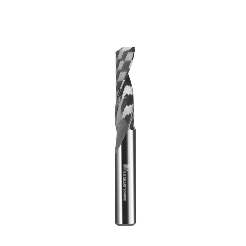
An upcut end mill features a helical spiral that twists upward from the tip toward the shank. As the spindle rotates, this geometry acts like a mechanical auger. It grabs the sheared material and pulls it vertically out of the cut channel. This active evacuation continuously clears the trench. It stops the tool from grinding up previously cut chips, which is the leading cause of premature tool wear.
This upward shearing action creates specific force vectors you must manage. The geometry exerts a strong upward axial force on the workpiece. At the same time, it pulls the router spindle downward into the cut. The tool physically tries to rip the material off the spoilboard while dragging the Z-axis deeper. You have to account for these forces when setting up your clamps and checking your Z-axis eccentric nuts for play.
Comparing this to other geometries helps clarify the application. Downcut bits use a reverse spiral. They push chips downward, compressing the top edge of the material for a clean finish, but they trap chips at the bottom of the trench. Compression bits combine both upcut and downcut spirals to shear the top and bottom edges inward. Upcut geometries ignore top-edge finish entirely to prioritize maximum chip extraction and heat removal.
Machining non-ferrous metals like 6061-T6 or 7075 aluminum pushes lightweight machines to their breaking point. Desktop routers flex under heavy lateral cutting forces. This gantry deflection causes chatter, ruins dimensional accuracy, and shatters carbide. Aluminum also has a relatively low melting point, making it highly vulnerable to friction.
Single flute upcut end mills stop aluminum from galling. Galling happens when aluminum heats up, turns soft, and friction-welds itself to the carbide cutting edge. Once aluminum sticks to the flute, the tool loses its sharp edge and breaks within seconds. By ejecting chips rapidly before they absorb too much heat, the upcut geometry removes the thermal energy from the cut zone entirely.
For roughing operations, single flutes are mandatory on hobby machines. Roughing requires clearing bulk material quickly without stalling the spindle. Single flutes handle this heavy lifting easily. Some machinists swap to a 2-flute bit for the final finishing pass to achieve a smoother wall finish, taking a very light radial stepover. But for the initial bulk removal, the single flute does the actual work.
Plastics demand excellent heat management. Materials like cast acrylic, extruded acrylic, polycarbonate, and High-Density Polyethylene (HDPE) melt fast when exposed to a rubbing tool. If your feed rate drops too low or your chip evacuation fails, the tool turns the plastic into a molten mess.
The aggressive chip evacuation of an upcut single flute stops chip re-welding. When you cut a deep slot in acrylic, trapped chips will melt and fuse back onto the freshly cut walls behind the bit. The upcut spiral physically lifts the plastic chips out of the channel before they have time to melt. This rapid extraction leaves a clean, frosted, or clear finish depending on the specific plastic grade.
Deep slotting creates a confined trench where chips have nowhere to go. When you cut a channel deeper than the diameter of the tool, coolant nozzles and compressed air blasts struggle to reach the bottom. Chips pile up fast in this tight space, leading to chip packing.
The upcut geometry acts as a physical pump in these situations. It does not rely on external air pressure to clear the hole. The rotation of the flute grabs the material and pulls it vertically out of the slot. This guarantees continuous material removal and stops the chips from binding against the tool shank.
You must calculate your feeds and speeds based on your machine's hard limits. Many hobby CNCs use palm routers, like the Makita RT0701C or DeWalt DWP611, as their spindle. These routers spin fast, typically between 10,000 and 30,000 RPM. They lose all their torque if you try to run them slower.
To avoid burning material at 20,000 RPM, you need a high feed rate. Because lightweight machines cannot feed fast enough to support multi-flute bits at these speeds, dropping to a single flute is the only way to maintain a proper chip load. Single flute bits thrive in high-speed, light-cut strategies. Instead of plowing a 0.25-inch depth of cut at 20 IPM, you take a shallow 0.05-inch depth of cut at 100 IPM. This high-speed machining approach reduces the lateral forces on the gantry and minimizes deflection.
Feed Rate Comparison for 0.002" Chip Load at 20,000 RPM
| Flute Count | Target Chip Load | Required Feed Rate (IPM) | Hobby CNC Feasibility |
|---|---|---|---|
| 1 Flute | 0.002" | 40 IPM | Excellent - Well within machine limits |
| 2 Flutes | 0.002" | 80 IPM | Marginal - May cause chatter on light frames |
| 3 Flutes | 0.002" | 120 IPM | Poor - Likely to lose steps or stall |
| 4 Flutes | 0.002" | 160 IPM | Fail - Exceeds rigidity and stepper torque |
Machine rigidity determines how much cutting force the frame can take before it bends. Single flute bits reduce overall cutting forces. With only one cutting edge hitting the material per revolution, the physical impact against the stock is cut in half compared to a 2-flute bit. Lower cutting forces mean less machine chatter and vibration.
You trade Material Removal Rates (MRR) for dimensional accuracy. Lightweight machines cannot push high MRR without the gantry twisting. When the gantry twists, the tool deflects, leaving you with tapered walls and ruined tolerances. The single flute geometry minimizes this deflection, letting lightweight machines cut precision parts at the cost of slightly longer cycle times.
The upcut geometry creates a massive risk of material lifting. As the flute shears the material upward, it applies a constant vertical pulling force on the stock. If your material is loose, the bit will rip the stock off the spoilboard. This destroys the part and snaps the end mill.
You need aggressive workholding. Standard double-sided tape fails on small parts because the upward force overcomes the adhesive. Use heavy mechanical clamping, like toe clamps or step blocks, whenever possible. For small parts where clamps get in the way of the toolpath, use the painters tape and cyanoacrylate (CA) glue method. Apply masking tape to the spoilboard and the back of the stock, then glue the two taped surfaces together. This provides massive shear strength against lifting forces.
Upcut bits ruin finish-grade woodworking. Wood is a fibrous material. When the upcut flute shears the wood, it pulls the fibers upward and away from the core. Because there is no material above the top surface to support these fibers, they splinter and tear out. This leaves severe fuzzing and jagged edges along the top cut line of Baltic birch or veneered plywood.
Use downcut or compression bits for clean top edges in woodworking. Downcut bits shear the fibers downward, pressing them against the core material and leaving a razor-sharp top edge. Compression bits shear both the top and bottom edges inward, giving you clean finishes on both sides of double-sided laminates.
Thin sheet metal and thin plastics fail predictably with upcut bits. Because these materials lack internal rigidity, the upward pulling force of the flute lifts the material right around the cut zone. The material rides up the flute of the spinning end mill like a helicopter rotor.
This localized lifting causes violent chatter. The material bounces up and down against the cutting edge. This ruins the dimensional accuracy, leaves a terrible surface finish, and shatters the end mill due to unpredictable shock loads. When machining thin stock, use a downcut bit to press the material flat against the spoilboard.
Industrial machines operate on completely different physics. They feature massive cast-iron frames, heavy linear profile rails, and high-torque servo motors. They do not care about the rigidity and feed rate limitations of desktop routers. A Haas or Datron can easily push a cutter through solid steel at 300 inches per minute.
In production environments, industrial machines use multi-flute end mills. A 3-flute or 4-flute end mill removes material three to four times faster than a single flute bit, assuming the machine has the horsepower to push it. Maximizing MRR and reducing cycle times dictates production profitability. Single flutes are inefficient and economically unviable in high-rigidity setups.
Dialing in feeds and speeds terrifies new operators. They worry a slight miscalculation will instantly destroy their tooling. Single flute bits offer a massive window for error. Because the gullet is so large, you can accidentally run the feed rate slightly too slow without immediately packing the flute and snapping the bit.
Follow this methodology to find the sweet spot for a new material:
You must use air blasts or mist coolant when cutting aluminum. Lubrication and cooling remain mandatory, even with upcut geometries. An air blast physically blows residual chips off the cutting path so the tool doesn't recut them. Mist coolant provides a thin layer of lubrication that stops the aluminum from sticking to the carbide edge.
Even with perfect math, operators encounter machining issues. Identifying the root cause quickly saves your tooling. Check your setup against common failure modes to get back on track.
Troubleshooting CNC Milling Failures
| Symptom | Probable Cause | Mitigation Strategy |
|---|---|---|
| Chatter and poor surface finish | Tool deflection or loose workholding | Check workholding rigidity. Reduce the depth of cut. Increase the feed rate slightly to stabilize the tool pressure. |
| Tool breakage (snapping at shank) | Chip packing or excessive feed rate | Clear the cut channel with compressed air. Verify the spindle is reaching the commanded RPM. Check the collet for runout. |
| Material melting (Plastics) | Feed rate too slow (rubbing) | Increase linear feed rate. Decrease spindle RPM. Ensure chips are evacuating completely from the slot. |
| Aluminum welding to flute (Galling) | Excessive heat generation | Apply mist coolant or WD-40. Increase feed rate to thicken the chip. Check the tool edge for dullness. |
| Top edge tear-out (Wood) | Upward shearing force on fibers | Switch to a downcut or compression end mill. Apply masking tape over the cut line before routing. |
A: Single flutes have larger chip gullets and require lower feed rates to achieve the same chip load, making them ideal for less rigid machines. 2-flute mills offer faster material removal and better finishes but require stiffer machines and faster feed rates.
A: Yes, particularly on desktop machines. They offer a wider margin of error for feeds and speeds, reducing the likelihood of burning material or snapping the bit while learning to calculate chip loads.
A: Yes, but with caveats. They clear chips well in deep pockets and reduce burning, but the upcut geometry will likely cause tear-out or fuzz on the top edge of the wood. Downcut or compression bits are generally preferred for wood finishes.
A: Hobby CNCs typically lack the rigidity to push a cutter fast enough to maintain proper chip load with multiple flutes. A single flute allows the machine to move slower while still making a proper chip, preventing the aluminum from heating up and melting to the bit.
A: It leaves a smooth finish on the bottom of the cut and the bottom edge of the material. However, the top edge may be rough or splintered due to the upward shearing force.
A: You must use robust workholding. Rely on mechanical clamps, strong vacuum tables, or the blue-tape-and-CA-glue method. Avoid standard double-sided tape for small parts when using upcut bits.
A: Moving too slowly causes the bit to rub rather than cut. This generates excessive heat, which can melt plastics, weld aluminum to the tool, and rapidly dull the cutting edge.