- All
- Product Name
- Product Keyword
- Product Model
- Product Summary
- Product Description
- Multi Field Search

Views: 0 Author: Site Editor Publish Time: 2026-08-20 Origin: Site
High-volume CNC woodworking demands tooling that sustains high RPMs and aggressive feed rates without dropping edge quality or causing machine downtime. Relying on standard High-Speed Steel (HSS) in automated production causes frequent tool changes and thermal degradation. You get poor surface finishes on abrasive materials like MDF and melamine, inflating labor and downtime. Transitioning to industrial-grade carbide wood cutting tools alters production efficiency. Standardizing your tool library with advanced materials lets you push feed rates higher while holding tight tolerances. We will break down the technical justification, performance metrics, and selection criteria for standardizing on carbide in a CNC environment. You need reliable cutting edges to keep spindles turning and parts moving off the table.
Defining the baseline requirements for CNC tooling starts with dimensional stability, heat evacuation, and edge retention over long production runs. When a spindle operates at 18,000 RPM, the friction generated at the cutting edge is massive. Tooling must withstand this continuous thermal load without losing its structural integrity. High-Speed Steel begins to lose its temper and soften at around 600 degrees Fahrenheit. In dense materials like particleboard, the cutting zone easily exceeds this temperature. If the cutting edge deforms or dulls prematurely, the machine operator must halt production, swap the tool, and recalibrate the machine zero point. This disrupts workflow and reduces daily throughput.
The metallurgical realities of tungsten carbide provide a massive operational advantage. Carbide is a composite material consisting of hard tungsten carbide particles bound together by a softer metal, typically cobalt. Industrial tooling relies on micro-grain and sub-micron structures. Smaller grain sizes allow for a sharper, more refined cutting edge because the particles pack closer together. The cobalt binder ratio directly affects the tool's performance profile. A lower cobalt content increases the overall hardness and wear resistance, making it ideal for abrasive composites. A higher cobalt ratio improves impact resistance, reducing the likelihood of chipping when cutting natural woods with inconsistent grain densities or hidden knots.
Modern industrial carbide tools often utilize specialized coatings to further enhance performance. Coatings such as Zirconium Nitride (ZrN) or Diamond-Like Carbon (DLC) create an ultra-hard barrier over the bare carbide. These coatings drastically reduce the coefficient of friction. Lower friction means less heat generation during aggressive cuts. These advanced coatings resist resin and pitch build-up. When cutting sappy woods like pine or adhesive-heavy materials like plywood, resin accumulation ruins a tool's geometry by filling in the flutes. Coated carbide sheds these materials, extending the functional life of the tool well beyond that of raw, uncoated carbide.
Heat dissipation and deflection resistance dictate how fast you can push a machine. Carbide possesses a significantly higher modulus of elasticity compared to steel. This immense rigidity prevents the tool from deflecting or bending under heavy lateral loads. When you push a 3/8-inch tool through 3/4-inch material at 800 inches per minute, tool deflection causes chatter marks on the workpiece. Chatter ruins the surface finish and forces your team to perform secondary sanding operations. The inherent stiffness of carbide ensures the cutting edge remains perfectly perpendicular to the material, guaranteeing precise tolerances and a flawless finish straight off the machine table.
Selecting the correct tooling format dictates your production efficiency. Production facilities must evaluate their specific applications to choose between solid carbide, brazed tooling, and insert systems. Each type offers distinct advantages and limitations based on the cutting profile, material density, and machine capabilities.
Solid carbide tools are manufactured from a single, continuous piece of carbide rod. They are best suited for high-precision cutting, small diameter requirements, and complex 3D profiling. The primary benefit of solid carbide is the ability to grind complex, continuous flute geometries. The flutes can be highly polished to facilitate rapid chip evacuation, which prevents heat buildup when plunging or cutting deep pockets in dense hardwoods.
Because the entire tool is made of carbide, it offers maximum rigidity and zero weak points along the shank. Solid carbide handles extreme lateral loads without snapping, provided the chip load is calculated correctly. When the cutting edge finally reaches the end of its usable life, the entire tool must be discarded or sent out for professional resharpening. For small diameters under half an inch, solid carbide remains the absolute standard for automated routing.
Carbide-tipped tooling features a steel body with pieces of carbide brazed onto the cutting edges. This format is best for large diameter profiles, such as spoilboard surfacing bits, large round-overs, and raised panel cutters. Manufacturing a three-inch diameter tool entirely from solid carbide is impractical for production due to the extreme weight and raw material requirements. Using a steel body keeps the tool weight manageable while placing the durable carbide exactly where it contacts the wood.
When evaluating brazed tooling, you must monitor the structural limitations of the brazed joint. The silver solder used to bond the carbide to the steel can fail under extreme heat or excessive chip loads. Operators must carefully monitor feed rates and ensure the tool does not overheat. Pushing a brazed tool too hard through dense material melts the solder, causing the carbide tip to shear off entirely. This poses a safety risk and instantly ruins the workpiece.
Insert carbide tooling utilizes a precision-machined steel or aluminum body that holds replaceable solid carbide knives. This system is best for high-volume production, cutting abrasive composites, and maintaining standardized edge profiles. Instead of replacing the entire tool when it dulls, the operator loosens a set screw, rotates or replaces the carbide insert, and resumes cutting in a matter of seconds.
The scalability of insert tooling streamlines large-scale manufacturing. Replacing only the cutting edge drastically reduces long-term consumable turnover. Insert tooling maintains a constant cutting diameter. When you resharpen a solid or brazed tool, the overall diameter shrinks. You must then update your CNC tool library and CAM software offsets to compensate for the smaller size. With insert tooling, a fresh knife guarantees the exact same diameter every time, eliminating software adjustments and reducing machine downtime.
The physical material of the tool is only half the equation. The shape and direction of the cutting edge determine how the tool interacts with the wood fibers. Selecting the correct carbide router bits requires a deep understanding of flute geometry and chip extraction dynamics. The flute acts as an auger, pulling waste material away from the cutting zone to prevent friction fires.
Upcut router bits feature a spiral that pulls chips upward and out of the cut channel. They excel at chip evacuation, which is absolutely required for deep pocketing or drilling operations. By rapidly clearing waste material, upcut bits prevent heat buildup and reduce the risk of tool breakage. The upward pulling action splinters the top surface of the material. When cutting veneered plywood or delicate laminates, an upcut bit pulls the veneer away from the core, causing severe top-edge tear-out.
Downcut router bits reverse this geometry. The spiral pushes chips downward into the cut channel. This downward shearing action leaves a pristine, splinter-free top edge, making it ideal for cutting dados or shallow grooves in finished materials. The drawback is poor chip evacuation. Because the waste material is packed down into the cut, downcut bits generate significantly more friction. You must adjust your feed rates and avoid deep, single-pass cuts to prevent the tool from overheating and burning the wood.
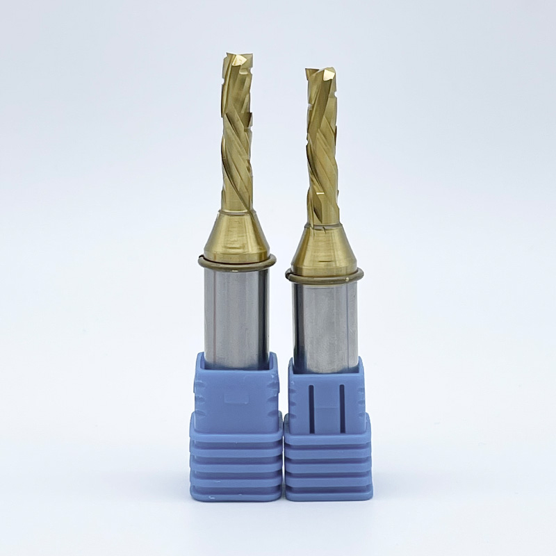
Solid carbide compression router bits are the undisputed industry standard for nested-based manufacturing. A compression bit combines both upcut and downcut geometries on the same cutting edge. The bottom portion of the bit features an upcut spiral, while the top portion features a downcut spiral. During the cut, these opposing forces push the chips toward the center of the material core.
This unique geometry exerts inward pressure on both the top and bottom surfaces of the workpiece simultaneously. The result is a flawless, tear-free edge on both sides of double-sided melamine, veneered plywood, and high-pressure laminates. To utilize a compression bit effectively, the first pass must plunge deep enough so that the upcut portion fully clears the bottom edge of the material. If the upcut section does not pass the bottom laminate layer, you will experience tear-out. When programmed correctly, compression bits eliminate the need for secondary edge finishing.
Translating metallurgical properties and flute geometries into actual shop floor results justifies tooling upgrades. The performance outcomes of carbide directly impact your daily throughput, material yield, and labor allocation. You measure success by how many sheets of material you can process before the spindle stops.
Edge retention in abrasive materials is the most immediate benefit. Manufactured sheet goods like Medium Density Fiberboard (MDF), Baltic birch plywood, and melamine contain dense glues, resins, and sometimes aluminum oxide particles. These binders act like sandpaper against a cutting edge. Standard steel tools dull rapidly, often losing their edge within a single sheet of material. Carbide performs exceptionally well against these glue lines. The extreme hardness of the micro-grain structure allows the tool to shear through abrasive binders without rounding over, maintaining a crisp edge for hundreds of sheets.
Feed rate optimization is another major production advantage. The rigidity and sustained sharpness of carbide allow operators to program aggressive chip loads. Instead of running a machine at 300 inches per minute to protect a fragile steel bit, you can push a high-quality carbide tool to 800 or 1,000 inches per minute, depending on the spindle horsepower. This directly reduces cycle times. Shorter cycle times mean you can process more sheets per shift, increasing your daily throughput without adding extra labor hours.
Tool life expectancy and spindle uptime are dramatically improved. Depending on the material density and resin content, a carbide tool typically lasts 10x to 50x longer than its steel counterpart. This translates directly into hours of saved machine downtime. Every time an operator stops the CNC to change a bit, you lose valuable production minutes. By extending the interval between tool changes, your spindle stays running, and your machine utilization rate climbs.
Surface finish quality is the final, and often most visible, performance outcome. A dull tool tears wood fibers, leaving a fuzzy or ridged surface. This forces your assembly team to spend hours manually sanding edges before applying edgebanding or finish. The sustained sharpness of carbide eliminates these secondary sanding operations. Parts come off the CNC router with glass-smooth edges, ready to move directly to the edgebander or the finishing room. This streamlined workflow reduces bottlenecks and lowers your overall labor burden.
Evaluating tooling requires looking past the initial acquisition. You must analyze the long-term production value and how the tool impacts your broader manufacturing efficiency. A lower-grade tool often ends up consuming significantly more resources in lost time and ruined material.
Calculating the true efficiency of a tool involves tracking machine downtime for tool changes, the logistics of resharpening, and the total linear feet cut during the tool's lifespan. While a carbide tool requires a larger initial setup than a steel tool, it cuts fifty times the linear footage. When you factor in the reduced machine downtime and the elimination of manual sanding, the efficiency per cut rises dramatically. High-volume shops cannot afford to run lower-grade tooling; the hidden labor of inefficiency slows down the entire factory floor.
The resharpening dilemma is a major factor in this efficiency analysis. Both solid carbide router bits and brazed tooling can be professionally resharpened. Grinding a fresh edge removes physical material from the tool. This reduces the overall cutting diameter. A half-inch bit may return from the sharpener measuring 0.485 inches. If the operator fails to update the CNC tool library and the CAM software offsets with this new diameter, all subsequent parts will be cut undersized. Managing these offsets requires meticulous record-keeping and introduces a high risk of human error. This hidden administrative labor pushes many production facilities toward insert tooling, where the diameter remains permanently fixed.
Tooling Format Application Guide
| Format | Ideal Application | Primary Advantage | Operational Limitation |
|---|---|---|---|
| Solid Carbide | Small diameters, 3D profiling, nested routing | Maximum rigidity, continuous flute geometry | Diameter loss on sharpening requires CAM updates |
| Carbide-Tipped (Brazed) | Large diameter profiles, spoilboard surfacing | Lightweight body for massive cutting diameters | Brazed joint vulnerable to extreme heat and shock |
| Insert Carbide | High-volume production, abrasive composites | Constant cutting diameter, rapid edge replacement | Limited to standardized edge profiles and straight cuts |
While carbide offers superior performance, it is not indestructible. Improper handling, incorrect programming, or poor machine maintenance will destroy a premium tool in seconds. Understanding and mitigating these risks ensures you maximize your tooling lifespan.
Managing carbide brittleness is your first priority. The primary vulnerability of tungsten carbide is its lack of tensile strength. It is incredibly hard but not flexible. Sudden shock loads, such as plunging too fast into dense hardwood, shatter the cutting edge. Simply dropping a carbide bit onto a concrete floor or letting tools clink together in a storage drawer causes microscopic fractures. These micro-fractures compromise the structural integrity of the bit, leading to catastrophic failure during operation. Tools must be stored in protective sleeves and handled with absolute care.
Calibrating feeds and speeds is mandatory. You cannot guess your cutting parameters. Running the spindle RPMs too high while keeping the feed rate too low causes the tool to rub against the material instead of slicing it. This rubbing generates extreme friction and heat buildup, which quickly burns the wood and degrades the carbide binder. You must calculate accurate chip loads. The chip acts as a heat sink, carrying thermal energy away from the tool. If the chip is too thin, the heat stays in the bit. Operators must use established formulas to balance RPM and feed rate for optimal chip thickness.
Dust extraction and chip packing present another major risk. Inadequate dust collection leaves waste material inside the cut channel. As the tool moves forward, it is forced to re-cut these loose chips. Re-cutting chips generates massive amounts of friction. In deep pocketing operations, packed chips create so much heat that they weld to the tool or cause the bit to snap entirely. A high-velocity dust extraction system is a required component of tool cooling and longevity.
Tool holding and runout mitigation require strict maintenance protocols. Precision collets, such as ER32 or ER40, must be kept immaculately clean. Dust or resin buildup inside the collet prevents it from gripping the tool shank evenly. This uneven grip causes runout, which is a microscopic wobble as the tool spins. Even a few thousandths of an inch of runout causes one flute to take a heavier chip load than the other. This vibration prematurely chips a carbide edge and ruins the surface finish of your parts.
Follow these steps for proper collet maintenance:
Upgrading to advanced tooling is a baseline requirement for any CNC shop prioritizing scale and precision. The ability to cut abrasive composites at high speeds without sacrificing edge quality directly impacts your production schedule. By understanding material properties and flute geometries, you optimize your entire manufacturing workflow.
A: Depending on material density and resin content, carbide lasts 10x to 50x longer than High-Speed Steel. When cutting highly abrasive materials like MDF or melamine, HSS dulls almost immediately. Carbide maintains a sharp cutting edge for hundreds of sheets, drastically reducing machine downtime and keeping production schedules on track.
A: Yes, they can be professionally resharpened. Grinding a new edge removes material, which reduces the overall cutting diameter of the bit. You must manually update your CNC tool library and CAM software offsets to account for this smaller diameter. Failing to update these offsets results in undersized parts and loose joints.
A: Chipping is usually caused by excessive spindle runout, incorrect chip loads, or dirty collets. Because carbide is brittle, any vibration or shock load fractures the edge. Chip packing from poor dust extraction or cutting through foreign materials hidden in the wood also causes immediate chipping.
A: These grades refer to the grain size and cobalt binder ratio. C4 is a finer micro-grain with less cobalt than C3. This makes C4 harder and more wear-resistant, ideal for abrasive composites like MDF. C4 is more brittle, making C3 a better choice for natural woods requiring higher impact resistance.
A: You must use a compression bit when cutting double-sided laminates, veneered plywood, or melamine. The combination of upcut and downcut flutes pulls the chips toward the center of the material, preventing both top and bottom edge tear-out. An upcut bit splinters the top surface of these materials.
A: Yes, they provide significant value if you run standardized profiles frequently. While the initial tool body requires a larger setup commitment, replacing the small carbide inserts streamlines operations. The breakeven scenario occurs after just a few tooling cycles through saved labor. You save immense time by never having to recalibrate tool diameters or update CAM software offsets after a tool change.
A: You calculate the required parameters using the standard chip load formula: Feed Rate = RPM × Number of Flutes × Target Chip Load. You determine the ideal chip load for your specific material and tool diameter, then adjust your RPM and feed rate to hit that exact target thickness.