- All
- Product Name
- Product Keyword
- Product Model
- Product Summary
- Product Description
- Multi Field Search

Views: 0 Author: Site Editor Publish Time: 2026-08-16 Origin: Site

Tooling selection directly dictates surface finish quality, spindle lifespan, and dimensional accuracy in any machining operation. Using the wrong cutter compromises the project before the spindle even reaches optimal RPM. A widespread problem across the shop floor involves operators using the terms "router bit" and "end mill" interchangeably. This confusion leads to incorrect feed and speed calculations, catastrophic tool failure during plunge cuts, and severe workpiece tear-out. Operators often assume a cutter designed for edge profiling can handle aggressive pocketing, resulting in broken shanks and ruined stock. Choosing between cnc router end mills and traditional router bits requires a strict technical evaluation. You must analyze tool geometry, material composition, machine rigidity, and specific cutting operations like profiling versus plunging. Understanding these mechanical differences prevents costly downtime and ensures predictable, repeatable cuts across different materials.
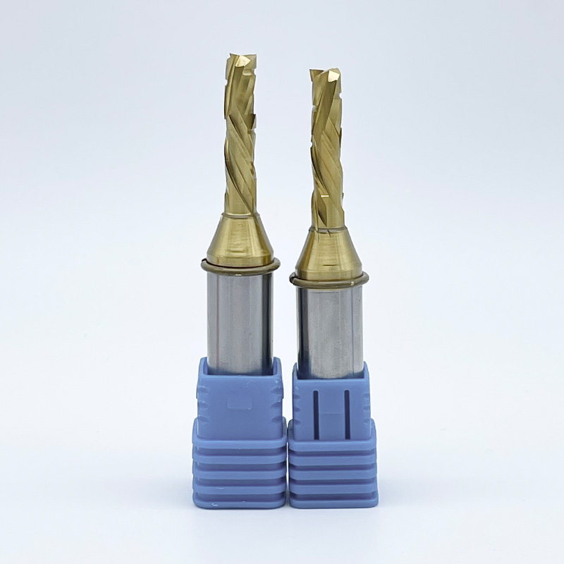
An end mill features a continuous, solid construction. Manufacturers typically grind these tools from solid micro-grain carbide blanks. The micro-grain structure prevents microscopic fractures along the cutting edge during heavy chip loads. The flutes wrap continuously around the tool body, terminating at a center-cutting tip geometry. This structural anatomy allows the tool to engage material aggressively from multiple directions. The primary function involves multi-directional cutting, meaning the tool can move simultaneously along the X, Y, and Z axes. This capability makes it the standard choice for 3D profiling, deep pocketing, and rapid material removal. When you need to clear out a deep pocket in a block of 6061 aluminum or hog out material for a hardwood tray, this is the tool you mount in the spindle.
A traditional router bit utilizes a composite construction. It consists of a hardened steel shank and body, with carbide cutting edges brazed onto the steel. These brazed inserts can be straight or ground into complex profiles like coves, chamfers, or round-overs. The primary function of a standard router bit is 2D lateral cutting along the X and Y axes. They excel at edge forming and surfacing spoilboards. However, they possess limited or zero Z-axis plunge capability because the center of the tool tip lacks cutting geometry. If you try to drive a standard straight bit directly down into a sheet of plywood, the center of the bit will simply burn and crush the wood fibers until the tool snaps.
Terminology overlap creates significant confusion when purchasing tooling. Woodworking catalogs frequently advertise "spiral router bits" for heavy material removal. Structurally and geometrically, these spiral bits are identical to end mills for CNC routers. The distinction exists purely in marketing nomenclature. Tooling suppliers use the term "spiral router bit" to appeal to traditional woodworkers transitioning to automated machines. From an engineering standpoint, if it features solid carbide construction, helical flutes, and a center-cutting tip, it is an end mill. You can take a spiral bit from a woodworking catalog and use it to mill aluminum if the geometry matches, proving the names are interchangeable on the shop floor.
Auditing a tool library requires quick visual identification. You can distinguish a mystery tool by inspecting specific areas. Follow this process to identify unknown cutters on your tool cart:
The physics of the bottom geometry dictate how a tool enters the material. Center-cutting tools feature cutting edges that extend all the way to the central axis. When the Z-axis lowers, these edges shear and evacuate material directly beneath the tool, functioning much like a drill bit. This allows for aggressive, vertical plunge cuts without pre-drilling. Standard bits lack this central cutting geometry. If you plunge a non-center-cutting bit straight down, the outer edges cut a circular path, but the dead center simply crushes against the stock. This leaves a core of uncut material beneath the tool. The resulting friction causes extreme heat buildup, rapid dulling of the carbide, severe burn marks on the workpiece, and often immediate tool breakage.
Solid carbide offers exceptional rigidity and wear resistance. This stiffness prevents the tool from bending under heavy lateral loads, ensuring tight dimensional tolerances during high-speed machining. However, this rigidity comes with a trade-off. Solid carbide is inherently brittle. Sudden shocks, excessive vibration, or dropping the tool on a concrete floor can cause it to snap or chip. Brazed bits utilize a steel body which provides distinct shock absorption benefits. When cutting natural wood with inconsistent grain patterns or knots, the steel body absorbs the impact of heavy, interrupted cuts. The brazed carbide inserts maintain a sharp edge, while the steel core flexes slightly to prevent catastrophic shattering. This makes brazed bits highly effective for large-diameter profiling operations where solid carbide would be dangerously brittle.
Helical flute geometries manage chip evacuation and edge finish. Upcut flutes pull chips upward and away from the cutting zone. This provides excellent heat dissipation but can cause tear-out on the top surface of the material. Downcut flutes push chips downward, leaving a pristine top edge but packing chips into the cut channel. This packing requires slower feed rates to prevent overheating. Compression flutes combine both upcut and downcut geometries on a single tool. They pull up from the bottom and push down from the top, directing all cutting forces toward the center of the material. This specific geometry prevents delamination when cutting double-sided veneered plywood or melamine. Traditional straight-flute bits simply chop the material laterally. They do not actively eject chips vertically, making them prone to heat buildup in deep slots.
Flute Geometry and Application Guide
| Flute Type | Chip Direction | Best Application | Finish Quality |
|---|---|---|---|
| Upcut | Upward | Deep pocketing, aluminum milling | Clean bottom, rough top |
| Downcut | Downward | Shallow dados, thin materials | Clean top, rough bottom |
| Compression | Toward Center | Double-sided laminates, plywood | Clean top and bottom |
| Straight | Neutral | General edge routing, plastics | Average on both sides |
Calculating chip load forms the foundation of efficient routing. Chip load represents the physical thickness of the material removed by a single cutting edge during one revolution. The number of flutes directly dictates the required feed rate at standard spindle speeds, which typically range from 10,000 to 24,000 RPM. A two-flute tool requires a faster feed rate than a single-flute tool at the same RPM to maintain the target chip thickness. Running feed rates too slowly presents a massive risk. If the tool moves too slowly, the cutting edge rubs against the material instead of shearing it. This rubbing generates extreme friction, leading to burnt wood, melted plastic, or work-hardened metal. Solid carbide tools operate efficiently at higher speeds and feed rates than traditional bits. This capability yields a significantly higher Material Removal Rate (MRR), drastically reducing cycle times and increasing overall production efficiency.
Lateral forces generated during routing naturally push the tool away from the cut path. This phenomenon is known as tool deflection. Excessive deflection causes chatter, poor surface finish, and dimensional inaccuracy. A solid carbide tool resists deflection far better than a standard 1/4-inch shank brazed bit. The continuous carbide structure maintains its column strength even under aggressive lateral loads. However, tool rigidity means nothing without machine rigidity. Gantry flex, linear bearing play, and spindle runout dictate whether you can fully utilize a high-performance cutter. If you mount a premium solid carbide tool in a lightweight, belt-driven hobby machine, the machine frame will flex before the tool deflects. This introduces severe chatter and often snaps the brittle carbide. Heavy-duty industrial machines provide the mass and stiffness required to push solid carbide tooling to its maximum MRR. You should regularly check your spindle runout with a dial indicator; anything over 0.001 inches will drastically reduce the life of a solid carbide cutter.
Material composition dictates tool selection in woodworking. Engineered composites like MDF, particleboard, and veneered plywood require specialized handling. Spiral geometries, specifically compression flutes, are mandatory for through-cuts, pocketing, and slotting in these materials. They cleanly shear the abrasive glues and prevent surface splintering. Traditional bits remain highly relevant for specific woodworking tasks. When a project requires edge treatments like chamfering, round-overs, or complex cove profiles, brazed bits are the standard choice. They are also ideal for V-carving text or flattening large spoilboards, where wide cutting diameters are necessary but deep plunging is not required.
Routing plastics introduces the challenge of heat management. Materials like cast acrylic, HDPE, and polycarbonate melt rapidly if friction builds up in the cut channel. Single-flute or O-flute geometries are absolute necessities for these applications. The open flute geometry provides massive chip clearance, allowing the tool to eject material before it heats up and re-welds behind the cutter. Standard bits fail consistently in acrylic applications. Their straight flutes or multi-flute designs trap chips against the cut wall. The lack of vertical chip evacuation causes the plastic to melt, wrap around the tool shank, and ultimately snap the cutter or ruin the workpiece.
Traditional brazed bits cannot be used for metal cutting under any circumstances. The cutting geometry, clearance angles, and brazed joints are not engineered to withstand the shear forces required to cut aluminum or brass. Attempting to cut metal with a standard woodworking bit will result in immediate tool destruction and potential operator injury from flying carbide shrapnel. Machining non-ferrous metals requires purpose-built aluminum-cutting tools. These tools feature specific specifications, including high helix angles (often 35 to 45 degrees) to evacuate sticky aluminum chips quickly. They utilize specialized coatings like Zirconium Nitride (ZrN) to prevent material adhesion and require maximum tool rigidity to prevent chatter and work hardening.
Evaluating tooling costs requires looking beyond the initial purchase price. Premium solid carbide tools carry a significantly higher upfront cost compared to cheaper brazed bits. However, solid carbide maintains a sharp cutting edge much longer, especially in abrasive materials like MDF or fiberglass. Operators must calculate the cost-per-linear-foot of cutting. A premium solid carbide tool that cuts cleanly for thousands of linear feet provides better value than a cheaper brazed bit that dulls and burns material after a few hundred feet. Factoring in tool wear, replacement frequency, and the labor cost of changing tools often justifies the higher initial investment in solid carbide.
Tool maintenance strategies shift depending on production volume. Solid carbide tools hold enough intrinsic value to justify professional regrinding. Sending dull tools out for resharpening restores the cutting edge at a fraction of the cost of buying new tools. This practice significantly lowers long-term tooling expenses for high-volume production shops. Conversely, standard brazed bits are generally treated as disposable consumables. The cost of shipping and regrinding a basic straight bit often exceeds its replacement value. For low-volume prototyping or hobbyist applications, utilizing cheaper disposable bits makes economic sense when tool life is not the primary bottleneck.
Tooling Economics and Production Scaling
| Feature | Solid Carbide Tooling | Brazed Router Bits |
|---|---|---|
| Acquisition Cost | High | Low to Medium |
| Resharpening Viability | Highly Economical | Rarely Economical (Disposable) |
| Ideal Production Scale | High-Volume Manufacturing | Prototyping / Edge Profiling |
| Tool Life Expectancy | Extended (High Wear Resistance) | Moderate (Prone to dulling in composites) |
Tool entry strategies dictate tool survival. When using non-center-cutting bits, you must mandate ramping or helical interpolation in your CAM programming. Ramping moves the tool laterally while simultaneously lowering it into the cut, allowing the side cutting edges to clear material before the dead center touches the stock. This prevents the crushing force that breaks non-plunging bits. Even with center-cutting tools, plunge rates must be carefully controlled. Establish safe vertical feed rates based on material hardness. Plunging too aggressively into dense hardwoods or aluminum overloads the flutes, causing chips to pack at the bottom of the hole and snapping the tool instantly.
Heat is the primary enemy of both the tool and the workpiece. Avoiding burn marks in wood and work-hardening in metals requires optimizing the depth of cut and maintaining aggressive feed rates. Taking shallow cuts at high RPMs causes the tool to rub. Instead, increase the depth of cut to engage more of the flute length, which distributes heat across a larger area of the carbide. Utilizing air blasts significantly mitigates heat buildup. A strong, continuous stream of compressed air clears chips from deep pockets, preventing recutting. In metal applications, clearing chips immediately stops the material from welding to the cutter, preserving tool life and ensuring a smooth surface finish.
A: Yes, you can use one in a handheld or table-mounted wood router, provided the collet size matches the tool shank. Because these tools are designed for rigid machines, they grab material aggressively. You must maintain a firm grip on the router and take shallow passes to prevent dangerous kickback.
A: No, traditional bits lack center-cutting geometry. Plunging them straight down leaves a core of uncut material, causing extreme friction, burning, and potential tool breakage. To enter the material safely with a standard bit, you must program a ramping toolpath or use helical interpolation.
A: Structurally and geometrically, yes. The term "spiral router bit" is primarily a marketing label used in the woodworking industry to describe solid carbide tools. Both feature helical flutes and center-cutting tips designed for multi-directional cutting and efficient chip evacuation.
A: Look at the tip and the body. A center-cutting tool has continuous flutes that meet at the dead center of the tip, and the body is machined from a single piece of solid carbide. A traditional bit has a visible gap at the center of the tip and features carbide inserts brazed onto a steel shank.
A: The best choice is a solid carbide, single or two-flute tool specifically ground for non-ferrous metals. These tools feature high helix angles (35-45 degrees) for rapid chip evacuation and often utilize specialized coatings like Zirconium Nitride (ZrN) to prevent the aluminum from welding to the cutting edge.
A: Feed rate is calculated using the formula: Feed Rate = Spindle RPM × Number of Flutes × Target Chip Load. You must determine the recommended chip load for your specific material and tool diameter, then adjust your RPM and feed rate to hit that target without exceeding your machine's rigidity limits.