Please Choose Your Language
- All
- Product Name
- Product Keyword
- Product Model
- Product Summary
- Product Description
- Multi Field Search

Views: 0 Author: Site Editor Publish Time: 2026-07-31 Origin: Site

Machining hardened mold steels reaching HRC 60 to 70 imposes extreme mechanical demands on your tooling and machine setup. Scrapped parts and excessive manual polishing drive up production costs and extend lead times. Shop floors constantly face the tension between achieving tight dimensional tolerances, maintaining acceptable cycle times, and preventing premature tool failure. Chipping, catastrophic breakage, and rapid flank wear remain constant threats when cutting materials this hard. Success in ultra-hard milling requires more than just purchasing the hardest tool available. You must align tool geometry, substrate composition, advanced coatings, and precise machining parameters. This strategic alignment helps achieve a "machining to zero" state, eliminating secondary finishing operations. By optimizing these variables, machinists stabilize cutting forces and ensure predictable tool life. We will explore how to select and deploy the right HRC70 carbide end mill for your specific application.
Geometry dictates finish: Selecting between ball nose, corner radius, and multi-flute profiles directly impacts stepover limits and surface roughness (Ra) in hardened steel.
Rigidity is non-negotiable: An HRC70 carbide end mill requires ultra-low runout tool holders (shrink fit or hydraulic) and rigid machine setups to prevent micro-chipping.
Heat management over chip evacuation: In ultra-hard steel, air blast is generally preferred over liquid coolant to prevent thermal shock and coating degradation.
Parameter precision: Depth of cut (Ap), stepover (Ae), and feed per tooth (Fz) must be tightly controlled to maintain stable cutting forces and predictable tool life.
Cutting materials at HRC 68-70 presents severe physical realities on the machine table. High cutting forces generate extreme temperatures directly at the cutting edge. Tool deflection becomes a primary concern during continuous engagement, especially with long-reach tools. Defining "machining to zero" means reducing or entirely eliminating manual benching and polishing. Manual polishing introduces human error and often alters critical mold geometries, leading to mismatched parting lines. A true precision mold finishing cutter must feature a highly accurate 180-degree contour profile tolerance. This accuracy, measured in microns, eliminates step-downs and surface waviness across complex 3D surfaces.
We evaluate tool success across several dimensions. Volumetric metal removal rate (MRR) must balance against tool life. Pushing a tool too hard in HRC70 material results in immediate edge failure. Surface finish consistency and dimensional accuracy over extended continuous cuts determine the ultimate value of the machining process. If a tool wears too quickly, the start of the toolpath will have a different dimension than the end, ruining the mold cavity.
| Machining Metric | Standard Steel (HRC 30-40) | Ultra-Hard Steel (HRC 65-70) |
|---|---|---|
| Primary Failure Mode | Gradual flank wear | Micro-chipping, thermal cracking |
| Coolant Strategy | Flood coolant | High-pressure air blast |
| Radial Engagement (Ae) | 10% - 40% of tool diameter | 1% - 3% of tool diameter |
| Tool Holder Requirement | ER Collet acceptable | Shrink fit or hydraulic mandatory |
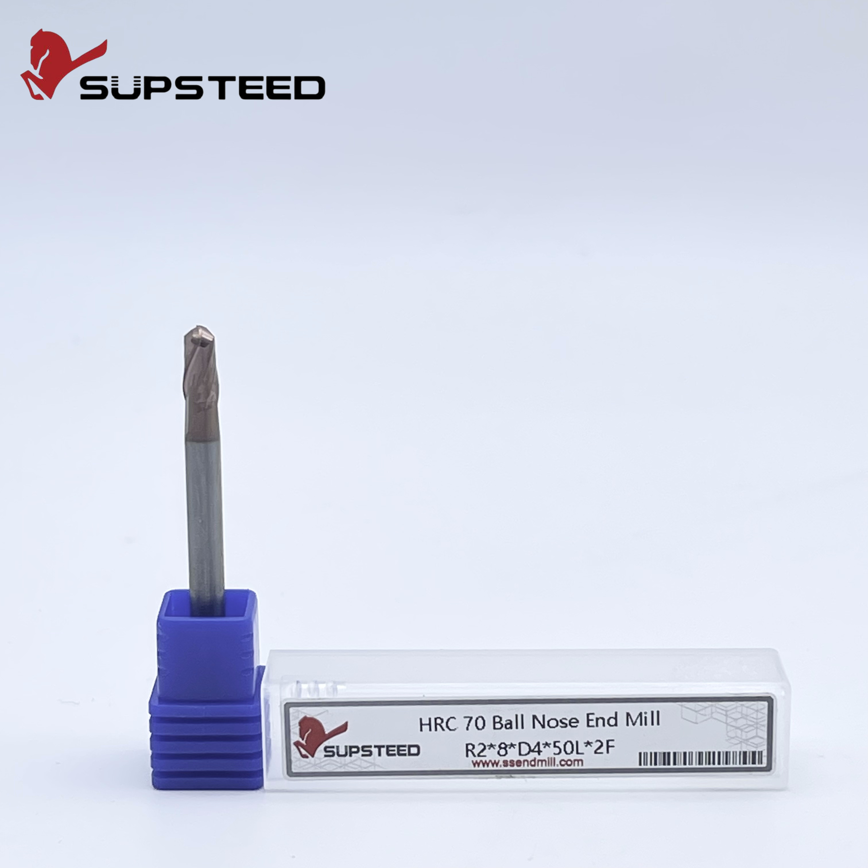
Complex 3D mold cavities require specific geometries to navigate steep walls and shallow floors. An HRC70 ball nose end mill excels in these profiling tasks. Machinists face the challenge of zero surface speed at the tool tip. When the tool cuts exactly on its center axis, the rotational velocity is zero, causing the tool to rub rather than shear the material. To counter this, tilt the tool or workpiece using 3+2 or full 5-axis machining. This engages the effective cutting diameter rather than the dead center. Stable edge strength at the center tip remains critical where cutting speeds approach zero, requiring specialized grinding techniques during tool manufacturing.
A corner radius strengthens the cutting edge significantly compared to square end mills. The sharp corner of a square end mill acts as a stress riser and will chip almost instantly in HRC70 steel. This geometry distributes cutting forces and reduces the risk of micro-chipping. An HRC70 corner radius end mill performs exceptionally well in roughing and semi-finishing. It also handles flat-surface finishing within mold bases effectively, leaving a superior floor finish while maintaining corner integrity.
Intricate mold details and narrow ribs demand small-diameter cutters under 2mm. These micro-tools face intense mechanical requirements. Runout amplification in micro-tools causes immediate failure. A 0.01mm runout on a 1mm tool is a massive percentage of its chip load. You must use precision tool-holder indexing and indexing devices during setup. Spindle warmup routines become mandatory to stabilize thermal growth before touching off these delicate tools.
Modern finishing shifts from traditional 2- or 4-flute designs to high-efficiency 6- or 7-flute configurations. Higher flute counts increase core strength and allow higher feed rates. They do reduce chip pocket volume, which remains acceptable in finishing where chip loads are minimal. Proper edge preparation includes micro-honed edges and negative rake angles. These features prevent edge chipping on any ultra hard steel end mill. The hone removes microscopic grinding burrs, leaving a stable, predictable cutting edge that can withstand the immense pressure of shearing hardened steel.
Realistic starting ranges for surface footage (Vc) and feed per tooth (Fz) require careful calculation. High-speed machining (HSM) dynamics utilize light cuts at high rotational speeds to optimize shear forces. Adjust these baselines based on tool diameter, overhang, and specific material composition. Pushing the feed rate too low causes rubbing and work hardening. Pushing it too high snaps the cutter.
Calculate the effective cutting diameter based on the depth of cut for ball nose tools.
Determine the base surface footage (SFM or Vc) recommended by the manufacturer for HRC70.
Calculate the spindle RPM using the effective cutting diameter.
Apply chip thinning formulas if the radial engagement (Ae) is less than 50% of the tool radius.
Set the machine feed rate based on the adjusted feed per tooth (Fz).
Optimal radial engagement (Ae) for finishing passes typically ranges from 1% to 3% of the tool diameter. This minimizes radial cutting forces and deflection, ensuring the tool cuts exactly where the CAM system thinks it is. Axial depth of cut (Ap) strategies vary. Contrast traditional profiling with deep axial trochoidal milling techniques to find the best approach. Trochoidal milling uses the entire flute length, spreading wear evenly across the carbide rather than concentrating it at the tip.
High-oxidation-temperature coatings like TiSiN or AlTiN thrive in the high-heat environment of HRC70 machining. These coatings form a protective oxide layer during the cut. This layer reduces friction and thermal transfer to the ultra-fine-grained carbide substrate. The substrate itself must possess high transverse rupture strength to resist the bending forces applied during the cut. Standard micro-grain carbide will not survive; you need ultra-fine or nano-grain structures.
Climb milling serves as the standard for finishing hardened steels. It achieves the best surface finish and directs heat into the chip rather than the workpiece. The chip starts thick and ends thin, reducing rubbing and heat generation. Conventional milling might be required in niche edge cases to mitigate severe deflection on long, thin walls, but it generally accelerates tool wear in HRC70 materials.
CAM software strategies maintain a constant chip load and engagement angle. This prevents spikes in cutting force that destroy rigid, brittle carbide tools in corners. Specialized 7-flute configurations execute deep axial cuts using large Ap and small Ae in stable setups. Morphing spiral toolpaths prevent sudden directional changes, keeping the machine motion smooth and the cutting forces consistent.
Arc-in, arc-out, or helical ramping movements are mandatory. Plunging straight into HRC70 material will cause immediate catastrophic tool failure. The center of an end mill has no chip evacuation space and zero cutting velocity. Always ramp in at a shallow angle, typically between 1 and 3 degrees, to ease the tool into the cut.
An advanced cutter cannot compensate for a loose machine. Maximum acceptable runout tolerances must stay below 0.003mm at the spindle nose. This prevents uneven chip loads and premature edge failure. If one flute takes a heavier chip than the others, it will chip, and the tool will fail rapidly. Check your spindle taper for fretting or damage regularly.
Shrink-fit or high-precision hydraulic chucks provide superior performance over standard ER collets. They maintain concentricity and maximize gripping force. ER collets introduce multiple mating surfaces, each adding potential runout. Shrink-fit holders grip the tool 360 degrees, providing maximum rigidity and dampening vibration during the cut.
Using flood coolant on carbide tools in hardened steel causes thermal shock and micro-cracking. The cutting edge heats up instantly in the cut and cools instantly when it exits, causing the carbide to expand and contract rapidly. High-pressure air blast or minimum quantity lubrication (MQL) clears chips without rapid temperature fluctuation. Position the air nozzles precisely to evacuate chips from deep cavities, preventing recutting.
Successfully deploying these tools requires a holistic approach combining rigid setups, specialized geometries, and highly controlled CAM parameters. Evaluate tooling partners based on their ability to provide specific, tested cutting data for HRC 65+ materials. Generic catalogs often fall short when dealing with extreme hardness.
Establish a controlled baseline test on a non-critical hardened block to verify parameters.
Verify spindle runout with a dial indicator before every critical finishing pass.
Update CAM libraries with verified chip thinning calculations for corner radius tools.
Implement a strict tool life management system based on time-in-cut rather than visual inspection.
A: The primary differences lie in substrate hardness, edge preparation, and coating oxidation temperatures. HRC70 tools utilize ultra-fine-grained carbide and specialized coatings designed to withstand extreme abrasive wear and higher heat generation. They also feature heavier edge hones to prevent micro-chipping under massive cutting pressures.
A: Premature chipping usually stems from excessive spindle runout, sudden spikes in chip load, thermal shock from liquid coolant, or improper entry toolpaths like straight plunging. A lack of machine rigidity or using standard ER collets also contributes heavily to edge failure.
A: You should use high-pressure air blast. Liquid coolant causes rapid thermal shock and micro-cracking in the carbide substrate due to extreme temperature fluctuations. Air blast effectively evacuates chips while maintaining stable tool temperatures.
A: The optimal stepover depends on the desired cusp height and surface finish (Ra) requirements. Typically, it ranges from 1% to 3% of the tool diameter for precision finishing passes. This small engagement minimizes radial deflection and ensures dimensional accuracy.
A: We advise against using standard ER collets for finishing operations due to runout stacking. Shrink fit or hydraulic holders provide the maximum concentricity and gripping force required to prevent micro-chipping in these brittle tools.
A: Feed rates require chip thinning calculations. The corner radius geometry distributes the cutting force differently than a square profile, meaning programmed feed rates must often increase to maintain the target chip thickness when taking light radial cuts.


