- All
- Product Name
- Product Keyword
- Product Model
- Product Summary
- Product Description
- Multi Field Search

Views: 0 Author: Site Editor Publish Time: 2026-08-24 Origin: Site
Ruined stock and excessive secondary finishing time destroy shop profitability. When tear-out, burning, or poor edge quality plagues a project, the root cause usually points directly to tooling selection. Wood is an anisotropic material. Its structural properties change drastically depending on the grain direction. Standard tooling approaches designed for isotropic materials like metal or plastics fail miserably here. Using the wrong tool results in frayed edges, packed chips, or snapped bits when applied to solid timber or engineered wood panels.
Achieving a flawless finish straight off the machine requires a calculated approach. You must match the end mill’s geometry, flute type, and material composition to the specific wood species and your machine's rigidity. Selecting the right cnc end mills for wood eliminates manual sanding, prevents material waste, and optimizes overall cycle times. Success depends on understanding how different cutting edges interact with wood fibers under high-speed rotation.
A clean cut in woodworking means the complete absence of tear-out, fuzzing, burning, and visible tool marks. Achieving this requires the cutting edge to shear the wood fibers cleanly rather than tearing or crushing them. The mechanics of the cut change continuously as the tool moves through the material. Cutting with the grain requires a different shearing action than cutting across the grain. When a tool cuts across the grain, it must sever the fibers completely. If the tool is dull or the geometry is incorrect, the fibers bend and snap, leaving a fuzzy or splintered surface.
Grain direction dictates the risk of tear-out. Solid wood consists of bundled cellulose fibers held together by lignin. Think of it like a bundle of drinking straws. Cutting parallel to the straws is relatively easy and produces long, stringy chips. Cutting perpendicular to the straws requires high shear force to cleanly slice the ends. If the cutting edge lacks the proper rake angle, it catches the fibers and pulls them out of the matrix. This creates deep voids in the material surface known as tear-out. Operators must constantly evaluate toolpath direction—specifically climb cutting versus conventional cutting—to manage how the cutting edge engages these fibers.
A common misconception is that metal cutting tools work perfectly fine for wood. While visually similar and sometimes interchangeable in a pinch, wood-specific CNC router bits for wood feature optimized rake angles and significantly larger gullets. Wood produces stringy, fibrous chips that expand after being cut. Metal end mills are designed for isotropic shearing and produce small, dense chips. Using a metal end mill on wood causes the small gullets to clog rapidly. Once the gullets pack with dust, the tool stops cutting and starts rubbing against the stock.
Friction is the enemy of wood machining. Wood burns rather than melts. When a tool rubs against the material instead of slicing it, friction generates intense heat. In metalworking, heat dissipates through the tool and the coolant. In woodworking, the tool must transfer heat directly into the chip. Efficient chip evacuation is the primary success metric for tool selection. If the chips stay in the cut channel, they recut, generating more friction until the wood scorches and the tool loses its temper. You must prioritize getting the chips out of the cut zone as fast as they are created.
Selecting the correct tool geometry determines where the chips go and how the finished edges look. Different operations demand specific flute orientations to manage chip flow and surface finish. Using the wrong geometry for a specific operation guarantees secondary cleanup work.
Upcut end mills feature flutes that twist upward, pulling chips up and out of the cutting channel. This geometry provides exceptional chip evacuation. They are best suited for deep slotting, high-volume material removal, and applications where the bottom-edge finish is the priority. Because the lifting action pulls the material upward, upcut bits tend to fray or splinter the top surface of the wood. They also exert an upward lifting force on the workpiece, requiring robust workholding to prevent the material from shifting during the cut. If your vacuum hold-down is weak, an upcut bit will lift the board right off the table.
Downcut end mills feature flutes that twist downward. This geometry shears the wood fibers downward, pushing chips into the cut channel. Downcut bits are ideal for shallow pockets, cutting thin or flexible stock, and achieving a flawless top surface finish. The downward pressure actually helps hold the material flat against the spoilboard. The major trade-off is poor chip evacuation. Because the chips are forced downward, deep cuts lead to rapid heat buildup, packed gullets, and potential tool breakage. Downcut tools should generally be limited to depths no greater than their diameter in a single pass.
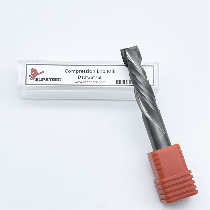
Compression end mills combine upcut geometry at the tip and downcut geometry on the shank. The flutes push the top fibers down and pull the bottom fibers up. This compresses the material toward the center of the cut. They are best for cutting double-sided laminated materials like plywood and melamine in a single pass. The result is a perfectly clean edge on both the top and bottom faces. The trade-off is that the first pass must cut deep enough to pass the upcut portion of the bit and engage the downcut section. If the first pass is too shallow, the tool acts purely as an upcut bit and splinters the top surface.
To successfully implement a compression bit, follow these setup steps:
Straight flute bits have cutting edges parallel to the tool axis. They offer neutral chip clearing, neither pulling up nor pushing down. They are excellent for general-purpose routing in solid wood where lifting or pressing the material is undesirable. They leave a clean edge but require slower feed rates due to less efficient chip extraction.
Fishtail and V-bits serve specific detailing functions. Fishtail geometries feature a flat bottom with a slight plunge point, making them perfect for flat-bottom pockets and sharp internal corners required in lettering or inlay work. V-bits are mandatory for chamfering edges, v-carving, and sign-making, allowing for variable width lines based on cutting depth.
Spoilboard surfacing cutters are maintenance tools. These multi-flute flattening bits maintain a perfectly trued Z-axis reference plane on the machine bed. Multiple flutes on these specific cutters aid in superior chip evacuation across wide areas. They produce a cleaner, flatter surface finish on the spoilboard itself, which directly translates to better accuracy and part hold-down for all subsequent jobs.
Comparison of Primary CNC Wood Router Bit Geometries
| Tool Type | Chip Direction | Top Edge Finish | Bottom Edge Finish | Best Application |
|---|---|---|---|---|
| Upcut | Upward | Prone to fraying | Clean and sharp | Deep slotting, fast clearing |
| Downcut | Downward | Clean and sharp | Prone to fraying | Shallow pockets, thin materials |
| Compression | Toward center | Clean and sharp | Clean and sharp | Double-sided laminates, plywood |
| Straight Flute | Neutral | Good | Good | General routing, neutral pressure |
Beyond the basic geometry, the technical specifications of the tool dictate its performance, longevity, and optimal running parameters. Evaluating these criteria ensures the tool matches the machine's capabilities and the material's properties.
The number of flutes on a router bit directly determines the available gullet space for chip evacuation and the required feed rate. A 1-flute bit offers maximum chip clearance. It is the best choice for high-speed routing in softwoods or plastics where large, stringy chips must be ejected rapidly to prevent melting or burning. A 2-flute bit provides the standard balance of finish quality and clearance, making it the workhorse for most solid wood and plywood applications.
Bits with 3 or more flutes require significantly higher feed rates to maintain an appropriate chip load. If a 3-flute bit is fed too slowly, the cutting edges take microscopic bites, creating dust instead of chips. This friction causes rapid heat buildup, burning the wood and dulling the tool. High flute counts are generally reserved for highly rigid, industrial CNC machines capable of sustaining very fast feed rates, often exceeding 600 inches per minute (IPM).
The material composition of the end mill dictates its wear resistance and edge retention. Solid Carbide is the industry standard for CNC woodworking. It is incredibly stiff and holds a sharp edge even when cutting highly abrasive glues found in MDF and plywood. Solid carbide tools resist heat deformation better than other materials, ensuring consistent cut quality over long production runs.
Carbide-Tipped tools feature a steel body with brazed carbide cutting edges. They are economical for large diameter tools, such as spoilboard surfacers or large profile bits, where solid carbide would be prohibitively expensive. High-Speed Steel (HSS) takes a sharper initial edge than carbide, making it excellent for hand-routing softwoods. However, HSS dulls rapidly when subjected to the high speeds and abrasive composites common in CNC routing. It is rarely recommended for production CNC work.
Tool Material Performance Characteristics
| Material Type | Edge Sharpness | Wear Resistance | Best Use Case |
|---|---|---|---|
| Solid Carbide | High | Excellent | Production routing, MDF, Plywood |
| Carbide-Tipped | High | Good | Large diameter profiling, surfacing |
| High-Speed Steel (HSS) | Very High | Poor | Low-volume softwood cutting |
Tool rigidity is paramount for clean cutting. Deflection occurs when lateral cutting forces bend the tool away from the intended path. This causes chatter, poor surface finish, and dimensional inaccuracy. The mathematical relationship between tool length and rigidity is severe. If you double the length of a tool, it becomes eight times more prone to deflection.
The golden rule for tool selection is to minimize stick-out. The cutting edge length (CEL) should only exceed the maximum depth of cut by 2–5 mm. Avoid excessively long bits. If you are cutting 18mm plywood, a tool with a 22mm CEL is ideal. Using a tool with a 50mm CEL for the same job introduces unnecessary vibration, degrades the cut quality, and increases the risk of snapping the bit.
Larger diameter tools offer greater rigidity and faster material removal rates. However, they cannot cut tight internal radii. Rest-machining is the strategic process of using a large clearing bit for the bulk of the pocket, followed by a smaller diameter end mill (e.g., 1/8" or 1/16") for secondary clean-up passes.
Stepping down to a smaller bit is essential for clearing out tight internal corners, achieving crisp edges on intricate lettering, and finalizing complex geometries. When programming rest-machining, ensure the smaller tool only engages the material left behind by the larger tool. Plunging a delicate 1/16" bit into full-depth stock will result in instant breakage. Always verify your toolpath simulation to confirm the small bit is only taking light finishing passes.
Wood is not a uniform substrate. The density, resin content, and grain structure vary wildly between species and manufactured panels. Tool selection must adapt to these material-specific characteristics to maintain cut quality.
Hardwoods possess dense, tightly packed fiber structures. They require exceptionally sharp edges and highly rigid machine setups to prevent chatter. A 2-flute upcut or downcut bit is the standard choice. Dense woods like cherry and maple are highly susceptible to burning if the feed rate drops or the tool dwells in corners. Optimizing the chip load is mandatory here. You must push the tool fast enough to create distinct chips that carry the heat away from the cut. If the chips look like fine powder, the feed rate is too slow or the RPM is too high. A standard starting point for hardwoods is 18,000 RPM at 200 to 250 IPM, adjusting based on the specific bit diameter.
Softwoods have loose, porous fiber structures. They are prone to fuzzing, tearing, and crushing rather than clean shearing. Standard 2-flute bits often struggle to clear the large, stringy chips produced by softwoods, leading to packed flutes. Single-flute or highly polished O-flute bits work exceptionally well in these materials. The massive gullet space evacuates the stringy chips quickly, and the single cutting edge provides an aggressive shearing action that slices through the soft fibers without crushing them. Climb cutting is often preferred in softwoods to compress the fibers ahead of the cut, reducing tear-out.
Engineered woods are highly abrasive due to the dense concentration of glues, resins, and binders used in their manufacturing. These chemicals act like sandpaper on cutting edges. Solid carbide tooling is mandatory to achieve an acceptable tool life. For through-cuts in double-sided veneered plywood or melamine, compression bits are non-negotiable. They are the only tools capable of preventing veneer chipping on both the top and bottom faces simultaneously. MDF machines easily but produces fine, abrasive dust that requires excellent dust extraction to prevent recutting and heat buildup. When cutting Baltic Birch plywood, operators must account for the dense core layers, which require slightly slower feed rates than standard softwood plywood.
Even the highest quality tool will perform poorly if implemented incorrectly. Understanding the dynamic variables of the cutting process allows operators to troubleshoot defects and optimize performance on the shop floor.
Wood burn is the most common defect in CNC routing. It is entirely a function of heat generation caused by improper feeds and speeds. The relationship between spindle RPM, feed rate, and flute count determines the chip thickness (chip load). If a bit is burning the wood, it means the tool is rubbing rather than cutting.
To fix wood burn, the operator must increase the chip thickness. This is achieved by either increasing the feed rate (moving the tool faster through the material), decreasing the spindle RPM (taking fewer bites per inch of travel), or switching to a bit with fewer flutes. Never reduce the feed rate to solve a burning issue; slowing down only increases friction and makes the burning worse. Always keep the tool moving. Dwelling in corners or pausing the program while the spindle is running will instantly scorch the material.
Tool breakage disrupts production and damages workpieces. Snapped tools are usually the result of aggressive plunge rates, inadequate chip clearing, or excessive deflection. Downcut bits are particularly prone to snapping in deep slots because they pack the chips downward, creating immense pressure at the bottom of the cut.
To mitigate breakage, utilize ramping toolpaths instead of straight plunging. Ramping enters the material at an angle, distributing the cutting force along the side of the tool and allowing chips to escape. For deep cuts, utilize multiple shallow passes rather than a single full-depth cut. Always ensure the tool shank is inserted fully into the collet (at least 75% of the shank length) to maximize rigidity. Clean your collets regularly; dust buildup inside the collet causes runout, which leads to premature tool failure.
Poor workholding mimics a dull tool. If the material vibrates or shifts even slightly during the cut, the cutting edge cannot shear the fibers cleanly. This vibration degrades cut quality, causes chatter marks, and rapidly dulls the tool. Vacuum tables must have adequate flow, and mechanical clamps must be positioned close to the cutting area.
The integrity of the spoilboard is equally vital. A deeply rutted or uneven spoilboard prevents the material from sitting flat. This compromises the effectiveness of compression bits, as the downcut/upcut transition zone relies on precise depth control. A freshly surfaced spoilboard ensures maximum vacuum hold-down, perfectly perpendicular cuts, and prevents tear-out on the bottom face of the workpiece. Resurface your spoilboard the moment you notice inconsistent cut depths or vacuum leaks.
There is no single universal end mill for CNC woodworking. Tool selection is strictly dictated by the material type, the grain direction, and whether the top, bottom, or both edges require a pristine finish. Using the correct geometry and maintaining optimal rigidity separates professional results from costly, time-consuming failures. By understanding the physics of chip evacuation and heat management, operators can eliminate manual sanding and maximize machine throughput.
For a production shop, building a baseline starter kit covers most applications. This should include a 1/4" downcut bit for clean pockets, a 1/4" compression bit for plywood profiles, a small diameter fishtail for intricate detailing, and a robust multi-flute surfacing bit for spoilboard maintenance.
To optimize your cutting process, follow these next steps:
A: An upcut end mill pulls chips upward, providing excellent evacuation for deep cuts but fraying the top edge of the wood. A downcut end mill pushes chips downward, leaving a perfectly clean top edge but packing chips into the cut, which can cause heat buildup in deep slots.
A: While possible in emergencies, it is not recommended. Metal end mills have smaller gullets and different rake angles designed for isotropic materials. When used on wood, they quickly clog with fibrous dust, leading to friction, burning, and poor edge quality.
A: Two flutes are the standard for most solid wood and plywood applications, offering a good balance of finish and chip clearance. Single-flute bits are excellent for softwoods to clear large chips rapidly. Three or more flutes require very high feed rates to prevent burning.
A: Burning is caused by friction when the tool rubs instead of cutting, usually due to a chip load that is too small. To fix it, you must increase the chip thickness by increasing your feed rate, decreasing your spindle RPM, or using a tool with fewer flutes.
A: A compression end mill combines upcut geometry at the tip and downcut geometry on the shank, pulling the material toward the center. It is used specifically for cutting double-sided laminated materials like plywood or melamine to achieve clean, chip-free edges on both faces.
A: The cutting edge length (CEL) should be as short as possible to maximize tool rigidity. A good rule of thumb is that the CEL should only exceed your maximum depth of cut by 2 to 5 mm. Excessively long bits cause deflection, chatter, and poor finishes.