- All
- Product Name
- Product Keyword
- Product Model
- Product Summary
- Product Description
- Multi Field Search

Views: 0 Author: Site Editor Publish Time: 2026-08-11 Origin: Site
Using incorrect tooling for non-metal machining directly inflates operational costs through high scrap rates, melted plastics, splintered wood, and delaminated composites. Wood, plastics, and composites possess vastly different thermal and structural properties than metals. Standard metal-cutting tools are inefficient and often destructive when applied to these softer or more abrasive substrates. Achieving pristine surface finishes, maximizing spindle uptime, and optimizing feed rates requires evaluating and selecting high-performance routing end mills based on material-specific geometries, flute counts, tip profiles, and carbide grades. We see shops lose thousands of dollars weekly just by running the wrong cutter geometry on acrylic or carbon fiber. You need to match the tool to the material's exact failure mode to maintain profitability and part quality.
Successful routing operations in non-metal materials are defined by strict physical outcomes: zero surface tear-out, complete absence of chip welding, strict dimensional accuracy, and maximized spindle uptime. Metal machining uses flood coolant to blast heat away from the cutting zone. Routing non-metals relies entirely on the tool's geometry to manage thermal loads and evacuate material rapidly. If you fail to manage heat and chip clearance, you get scrapped parts and damaged tooling. You also waste hours on manual post-processing tasks like sanding fuzzy edges or deburring melted plastic from the workpiece.
Wood is an anisotropic material. Its structural properties change entirely depending on the direction of the grain. Moisture content variations, hard knots, and alternating grain orientations require razor-sharp cutting edges. You have to shear the fibers cleanly rather than tearing them. Routing across the grain with standard tools causes severe splintering on the top or bottom edges. Specialized routing end mills designed for wood feature specific rake angles that slice through fibers, leaving a clean edge regardless of grain direction. Hardwoods like maple or oak require highly rigid tooling to prevent deflection, while softwoods like pine are prone to crushing if the rake angle isn't aggressive enough. We often see operators struggle with Baltic birch plywood because they use standard up-cut bits, resulting in massive veneer tear-out.
Plastics like acrylic, polycarbonate, and High-Density Polyethylene (HDPE) have extremely low melting points. The primary failure mode when routing plastics is friction-induced heat. If chips stay in the cut channel, they rub against the tool and the workpiece. This generates heat that melts the plastic instantly. The melted material then fuses to the cutter, causing chip welding. Once chip welding happens, the tool loses its cutting edge, friction spikes, and the tool snaps. Effective plastic routing demands massive chip clearance. You need rapid evacuation to keep the cutting zone cool. Cast acrylic chips easily and requires a scraping action, whereas extruded acrylic melts almost instantly and demands high feed rates combined with O-flute geometries.
Carbon Fiber Reinforced Polymers (CFRP) and fiberglass present extreme abrasiveness and structural fragility. The fibers act like sandpaper against cutting edges. They rapidly dull standard steel or low-grade carbide tools. Composites are manufactured in layers held together by resin. If a tool exerts excessive upward or downward force, it pulls these layers apart, causing delamination. Machining composites successfully requires highly abrasion-resistant materials and specialized geometries that neutralize vertical cutting forces. FR4 (fiberglass) creates highly abrasive dust that destroys spindle bearings if not extracted properly. Carbon fiber requires specialized burr-style routers to sever the high-tensile fibers without pulling them out of the resin matrix.
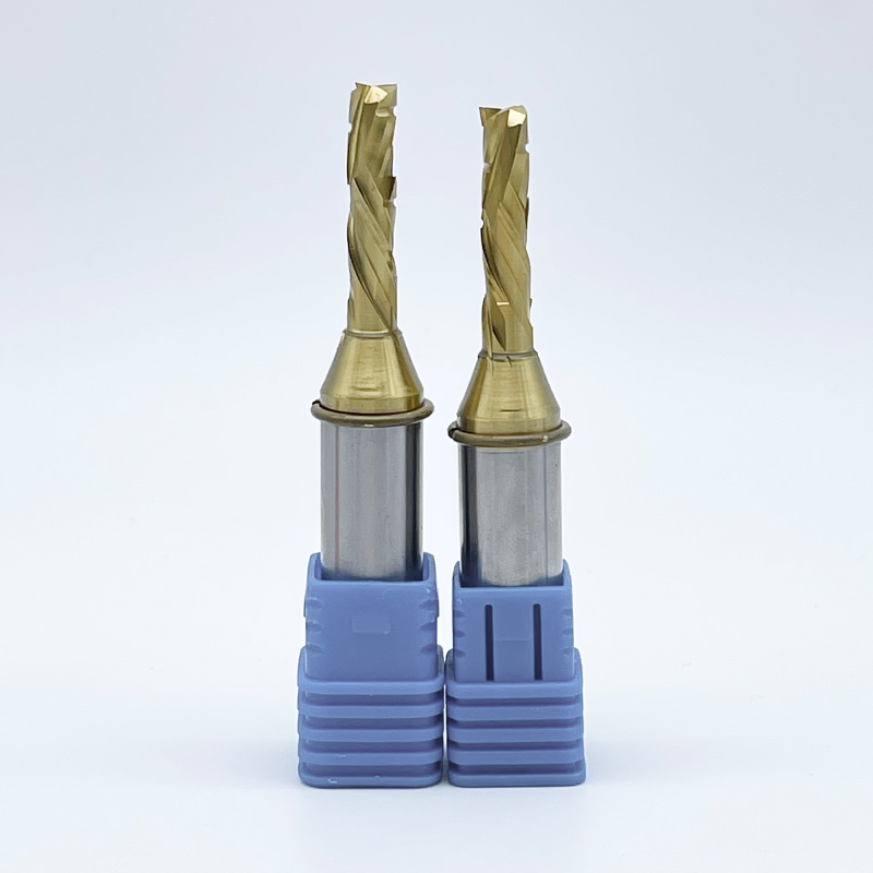
Standard general-purpose end mills are engineered for ferrous metals. They withstand high impact forces and break continuous metal chips. Applying these to non-metals usually results in immediate failure. High-performance variants are engineered specifically for wood, plastics, and composites. They feature higher rake angles for sharper shearing action. They have deeper flutes for enhanced chip evacuation. Specific helix configurations manage the unique structural integrity of non-ferrous and non-metal substrates. You cannot expect a tool designed to cut steel to perform well on a sheet of polycarbonate.
Structural rigidity and wear resistance dictate operational lifespan. High-Speed Steel (HSS) offers flexibility and impact resistance for basic, low-volume tasks. However, HSS dulls rapidly when exposed to abrasive materials or high-speed routing environments. High-performance tools almost exclusively utilize solid sub-micrograin carbide. This advanced carbide matrix provides exceptional hardness and edge retention. It allows the tool to maintain a razor-sharp cutting edge over extended production runs. You absolutely need this hardness when processing highly abrasive fiberglass or carbon fiber, where HSS would lose its edge in a matter of minutes.
Surface friction is the enemy in non-metal machining. High-performance tools undergo rigorous edge preparation and flute polishing. A mirror finish inside the flutes significantly reduces the coefficient of friction. For plastics and softwoods, this polished surface prevents sticky chips from adhering to the cutter. It ensures smooth, continuous evacuation. Lower friction directly correlates to lower cutting temperatures. This preserves the integrity of both the tool and the heat-sensitive workpiece. Unpolished flutes trap dust and chips, which acts as an insulator and rapidly overheats the cutting edge.
Selecting the correct flute count balances feed rate capabilities and chip clearance requirements. You must match the flute count to the material's chip formation characteristics.
The helix direction determines how cutting forces apply to the material. This affects surface finish and part stability on the machine bed.
The tip profile dictates the shape of the cut and the structural integrity of the machined feature.
Routing operations often require the tool to enter the material vertically. Center-cutting geometries feature cutting edges that extend all the way to the center of the tool axis. This allows straight plunging operations like drilling or deep mortising. Non-center-cutting tools have a void in the center of the tip. They cannot plunge straight down. They require ramping or helical entries to penetrate the material without crushing it. Always verify if your tool is center-cutting before programming a straight Z-axis plunge.
Tool rigidity is governed by its diameter and the Length of Cut (LOC). Use the largest diameter and the shortest LOC possible for the application. Excessive LOC increases the tool's susceptibility to deflection. Deflection causes chatter, poor surface finish, dimensional inaccuracy, and tool breakage. Select an LOC that is only slightly longer than the maximum depth of cut required. If you are cutting 0.5-inch plywood, using a tool with a 1.5-inch LOC introduces unnecessary vibration and weakens the setup.
Coatings alter the surface properties of the carbide to enhance performance. Wood and soft plastics often perform best with uncoated, highly polished solid carbide. Coatings can slightly dull the razor-sharp edge required for these materials. Abrasive composites demand protection. Coatings like Zirconium Nitride (ZrN), Diamond-Like Carbon (DLC), or Chemical Vapor Deposition (CVD) diamond withstand the extreme abrasion of carbon fiber and fiberglass. They drastically extend tool life and prevent the cutting edge from rounding over prematurely.
Tool Specification Matrix for Non-Metal Materials
| Material Category | Primary Failure Risk | Recommended Flute Count | Ideal Helix / Geometry | Coating Requirement |
|---|---|---|---|---|
| Solid Wood & Plywood | Tear-out, splintering | 2 Flutes | Compression or Down-cut | Uncoated (Polished) |
| Soft Plastics (HDPE) | Melting, chip welding | 1 Flute (O-Flute) | Up-cut for evacuation | Uncoated (Polished) |
| Hard Plastics (Acrylic) | Chipping, cracking | 1 or 2 Flutes | O-Flute or Bull Nose | Uncoated or ZrN |
| Abrasive Composites (CFRP) | Delamination, rapid wear | Multi-flute / Chipbreaker | Compression or Burr style | CVD Diamond or DLC |
When processing engineered panels like MDF, melamine, or veneered plywood, preserve the surface finish on both sides. Two-flute compression bits are the optimal choice for through-cuts in these materials. For shallow dadoes or pockets where the tool does not penetrate the entire sheet, down-cut bits ensure a crisp top edge. When cutting deep mortises in solid hardwoods, center-cutting flat end mills provide the necessary plunging capability and clean wall finishes. You must ensure your spindle has enough horsepower to drive compression bits through dense materials without bogging down.
Plastics require distinct approaches based on hardness. Soft, gummy plastics like HDPE require single O-flute geometries. The massive flute valley ensures large, continuous chips eject immediately before they melt. Hard, brittle plastics like cast acrylic are prone to chipping and cracking. These require specialized rake angles to scrape rather than gouge the material. Utilizing a bull nose profile prevents stress concentrations that lead to edge fracturing. Always use an air blast when routing plastics to clear chips mechanically and cool the cutting zone.
Carbon fiber and fiberglass destroy standard tooling in minutes. Operators must utilize multi-flute routers with diamond-patterned chipbreaker geometries. These tools grind composite fibers into fine dust rather than attempting to shear them. This reduces delamination risks. Utilizing CVD diamond-coated end mills is practically mandatory for high-volume composite routing. The diamond layer provides the extreme hardness required to resist abrasive wear. Ensure your dust collection system is rated for fine particulate matter, as composite dust is hazardous to both machinery and operators.
Selecting the right tool involves balancing operational speed, part quality, and tool longevity. Pushing a tool to its maximum feed rate increases throughput but accelerates wear and degrades surface finish. Running a tool too slowly reduces productivity and causes heat buildup due to rubbing. The return on investment for high-performance tooling is realized through the reduction of machine downtime for tool changes. It also eliminates manual edge sanding and drastically reduces scrapped parts. Spending more on a specialized cutter pays for itself if it saves you from scrapping a single sheet of expensive carbon fiber.
Maintaining the correct chip load is the most critical factor in routing. Chip load is the physical size of the material removed by each flute per revolution. The fundamental formula every operator must know is: Feed Rate equals Spindle RPM multiplied by the Number of Flutes multiplied by the Target Chip Load. If you increase RPM without increasing the feed rate, your chip load drops. The tool starts rubbing instead of cutting. This friction generates heat, which is the primary cause of tool failure in non-metals. Operators must consult baseline chip load data provided by manufacturers to dial in parameters. Always verify the manufacturer's maximum RPM ratings. Exceeding these limits can cause the tool to disintegrate under centrifugal force. This poses severe safety hazards and risks catastrophic spindle damage.
Adopting aggressive, high-performance tooling exposes weaknesses in machine setup. Tool runout is the microscopic wobble of the tool as it rotates. It is a primary cause of premature breakage. Runout disproportionately affects single-flute tools and tools with a long LOC. It forces one side of the cutter to take a massive chip load while the other side takes none. Operators must utilize highly rigid tool holding systems. Precision ER collets, hydraulic chucks, or shrink-fit holders are necessary. Regular spindle maintenance and collet replacement keep runout within acceptable tolerances. A dirty collet introduces runout instantly, so clean your tool holders before every tool change.
High-performance geometries exert significant forces on the workpiece. Aggressive up-cut tools generate massive vertical lifting forces. Compression tools create complex lateral pressures. If the material shifts even slightly during a high-speed routing operation, it will instantly snap the end mill and ruin the part. Implementing robust workholding is essential. This requires high-flow vacuum tables capable of maintaining strong downward pressure on porous materials like MDF spoilboards. Heavy-duty mechanical clamping systems are needed for smaller, discrete parts. Ensure your vacuum zones are properly gasketed to concentrate holding power exactly where the cutting forces are applied.
When surface finish degrades, operators must identify the root cause immediately. Burn marks on wood indicate the feed rate is too slow or the spindle RPM is too high. This causes the tool to rub and scorch the material. Fuzzy edges on MDF or plywood suggest the tool is dull or the wrong helix direction is being used. Switch to a compression bit to resolve fuzzy top and bottom edges. If you see chatter marks on plastic, your tool is deflecting.
Chatter leaves a wavy, inconsistent pattern on the cut edge. It stems from tool deflection. If you experience chatter, reduce the Length of Cut (LOC) to the absolute minimum required for the job. Increase the tool diameter if the design allows. You can also reduce the depth of cut per pass. Ensure the collet is clean and properly torqued. Debris inside the collet introduces runout, which amplifies chatter and destroys surface finishes.
If chips pack into the cut channel, the tool will break. This happens frequently when slotting deep pockets in plastic or aluminum. To fix this, switch to a single-flute up-cut tool to maximize evacuation. Add an air blast system to clear chips from the cutting zone mechanically. Never use liquid coolant on wood or MDF, as it swells the material. Use compressed air to keep the tool cool and the path clear.
Common Routing Defects and Solutions
| Defect Observed | Probable Cause | Immediate Action / Solution |
|---|---|---|
| Burn marks on wood | RPM too high, feed too slow | Increase feed rate, decrease spindle RPM |
| Melted plastic on tool | Poor chip evacuation, friction | Switch to O-flute, increase feed rate, add air blast |
| Tear-out on top veneer | Up-cut geometry lifting fibers | Switch to down-cut or compression geometry |
| Delamination in CFRP | Excessive vertical cutting force | Use diamond-pattern chipbreaker or compression bit |
| Wavy edge finish (Chatter) | Tool deflection, excessive LOC | Use shorter LOC, larger diameter, or reduce pass depth |
A: The best choice is a single-flute O-flute solid carbide end mill. Soft plastics like HDPE require massive chip clearance to prevent heat buildup. The single-flute design, combined with highly polished flutes, ensures rapid chip evacuation and prevents the plastic from melting and welding to the cutter.
A: Use a compression end mill when cutting double-sided laminates, veneered plywood, and melamine. The geometry pulls the bottom edge up and pushes the top edge down, directing cutting forces toward the center. This prevents splintering and tear-out on both the top and bottom faces of the material.
A: Plastics melt due to friction-induced heat caused by incorrect machining parameters. High spindle speeds combined with low feed rates cause the tool to rub against the material rather than shearing it. Inadequate chip evacuation also traps hot chips in the cutting zone, accelerating the melting process.
A: No, standard metal tools fail on non-metals. They feature incorrect rake angles that crush rather than shear wood fibers, insufficient chip clearance that causes plastics to melt, and unpolished flutes that trap heat. Composites will also rapidly destroy the cutting edges of standard metal-cutting tools.
A: Two-flute designs are the industry standard for routing wood. They offer the best balance between surface finish quality and feed rate capabilities. A two-flute tool provides enough valley space for efficient chip and dust evacuation while maintaining structural rigidity for fast routing.
A: Center-cutting end mills have cutting edges that extend to the center of the tool, allowing them to plunge straight down into material like a drill bit. Non-center-cutting tools have a void in the center and require ramping or helical entry paths to penetrate the material without crushing it.