- All
- Product Name
- Product Keyword
- Product Model
- Product Summary
- Product Description
- Multi Field Search

Views: 0 Author: Site Editor Publish Time: 2026-08-12 Origin: Site

Defaulting to sharp-cornered flat end mills for heavy roughing carries a hidden operational penalty. Machinists frequently encounter premature edge chipping, forcing them to run suboptimal feed rates and driving up tool replacement frequency. A sharp 90-degree corner acts as a focal point for mechanical stress and heat accumulation. When that fragile tip engages hard materials or encounters interrupted cuts, micro-fractures develop rapidly, leading to catastrophic tool failure.
Manufacturing engineers and CNC programmers face a constant balancing act. They must adhere to strict part geometry tolerances—specifically inside corner radii specified on engineering prints—while maximizing Material Removal Rates (MRR) and extending tool life. Achieving this balance requires moving away from generic tooling choices and applying a systematic approach to tool selection.
Choosing the optimal radius involves evaluating material properties, toolpath strategies, and specific application constraints. By matching the correct radius to the operation, shops run more aggressive parameters, stabilize machining processes, and maintain edge integrity through long production cycles.
Defining a successful milling operation requires looking beyond simply removing metal. True success criteria involve achieving zero edge chipping throughout the tool's intended lifespan, meeting stringent surface finish specifications on the first pass, and consistently hitting target cycle times. When tools fail prematurely, cycle times inflate due to unplanned tool changes and scrapped parts. Selecting the correct tool geometry establishes the baseline for meeting these criteria.
Understanding the baseline differences between end mill profiles clarifies why specific shapes fail under high-stress conditions. Flat end mills feature a sharp 90-degree transition between the peripheral cutting edge and the bottom face. During heavy roughing, this sharp corner takes the brunt of the cutting force. Because there is no material mass supporting the very tip of the corner, it chips easily under heavy chip loads or vibration. Once the edge chips, the tool starts rubbing instead of shearing, causing heat to spike and the carbide to break down.
Ball nose end mills offer excellent strength because the cutting edge is a continuous curve, but they are highly inefficient for machining flat-bottom pockets. A ball nose tool leaves massive cusps on the floor of a pocket. You would need an incredibly small stepover to achieve a flat surface, which destroys your material removal rate.
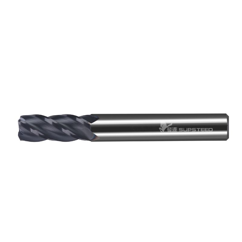
The bull nose profile bridges this gap. It provides a flat bottom for efficient floor machining while replacing the fragile 90-degree tip with a strengthened, curved transition. This geometry allows machinists to flat-bottom a pocket efficiently while retaining the edge strength necessary for aggressive roughing.
The physics of stress concentration explain why a radius drastically improves tool longevity. In mechanical engineering, sharp internal or external corners act as stress risers. When a flat end mill engages a workpiece, the cutting forces and generated heat concentrate directly on the sharp tip. The carbide matrix at this microscopic point lacks the structural support to withstand high shear forces.
Introducing a radius mitigates this focal point. A rounded corner distributes the mechanical stress and heat over a significantly larger surface area. Instead of a single point absorbing the impact of entering the cut, a broader section of the carbide edge shares the load. This distribution prevents the localized thermal shock and mechanical overload that cause micro-chipping. It also provides a larger surface area for heat to dissipate into the body of the tool, keeping the cutting edge cooler and intact longer.
Precision in terminology prevents costly tooling mistakes on the shop floor. A corner radius end mill, commonly called a bull nose, is designed for pocketing, slotting, and profiling operations where the machined part requires an inside radius at the floor-to-wall transition. The radius is built into the cutting edge of the tool itself.
Conversely, a corner rounding end mill is a specific form tool used exclusively to machine an outside radius onto the external edge of a part. You cannot use a corner rounding tool to mill a pocket, and you cannot use a standard bull nose end mill to put a perfect external quarter-circle edge break on a block. Understanding this distinction ensures the correct tool is pulled from the crib for the programmed operation.
Selecting the exact radius dimension is dictated by a combination of part design, material properties, and machining dynamics. Ignoring any of these variables leads to either scrapped parts or broken tools.
The golden rule of radius selection revolves around the engineering drawing. The tool's corner radius must always be equal to or slightly smaller than the required inside corner radius of the machined part. If a blueprint calls for a 0.125-inch inside corner radius, using a tool with a 0.187-inch radius will leave excess material in the corners, violating the part tolerance.
Using a tool with the exact same radius as the part specification is common but often problematic. When a 0.125-inch radius tool hits a 0.125-inch corner, tool engagement spikes to 90 degrees simultaneously. This sudden spike in tool engagement causes chatter, deflection, and frequently snaps the tool. Always select a tool radius slightly smaller than the print specification for finishing passes to prevent corner binding.
From an engineering perspective, part designers play a crucial role in machining efficiency. Design for Manufacturability dictates that engineers should specify inside corner radii slightly larger than standard fractional tool radii. For example, instead of calling out a 0.125-inch radius, designing the part with a 0.130-inch or 0.135-inch inside radius allows the machinist to use a standard 0.125-inch radius tool.
This slight clearance allows the CNC machine to interpolate the corner. The tool rolls through the corner using a smooth circular toolpath rather than burying itself into a sharp direction change. This dynamic motion maintains a consistent chip load, eliminates chatter, and drastically improves the surface finish of the final part.
The hardness and shear strength of the workpiece material directly dictate how large the tool radius needs to be. Softer materials like aluminum or brass exert lower cutting forces, allowing machinists to use smaller radii if tight corners are required. However, as material hardness increases, the demand for edge protection rises exponentially.
When machining aerospace alloys, tool steels, or hardened materials, utilizing solid carbide corner radius end mills becomes mandatory. Solid carbide provides the extreme rigidity and heat resistance required to shear tough metals. For materials like Inconel or Titanium, a larger radius is necessary to withstand the high cutting pressures and work-hardening tendencies of the metal. A small radius in these materials will chip almost immediately upon entry.
The chosen radius significantly impacts the effective cutting diameter of the tool at varying depths of cut. If the Axial Depth of Cut (ADOC) is shallower than the corner radius itself, the tool is not cutting on its full outer diameter. Instead, it is cutting entirely on the curved portion of the radius.
This scenario requires recalculating the effective cutting diameter to maintain the correct Surface Feet per Minute (SFM). Furthermore, cutting on the radius induces chip thinning. Because the cutting edge is angled relative to the workpiece, the actual chip thickness is less than the programmed feed per tooth. Programmers must increase the feed rate to achieve the target chip load; otherwise, the tool will rub against the material, generating excess heat and causing premature wear.
Every radius size carries inherent advantages and limitations. Machinists must weigh the need for precision in part geometry against the requirement for structural durability during heavy material removal.
Small radii are typically utilized when part designs demand tight inside corners or nearly flat-bottomed features. They allow the tool to machine closer to a true 90-degree intersection without leaving significant residual material.
The primary advantage is precision. A small radius minimizes the need for secondary rest-machining operations with smaller tools. However, the downside is fragility. A 0.015-inch radius offers minimal edge protection compared to larger profiles. These tools remain highly susceptible to chipping during interrupted cuts, when entering hard materials, or if the machine setup lacks absolute rigidity.
Medium to large radii are the workhorses of bulk material removal. By maximizing the curved surface area, these tools provide unparalleled edge strength and superior heat dissipation.
The main advantage is the ability to enable High-Efficiency Milling (HEM) toolpaths. A robust radius handles the high feed rates and deep axial cuts associated with modern roughing strategies. The trade-off involves residual material. A large radius leaves more stock in the corners of a pocket, which often necessitates a subsequent tool change to clean out the remaining material. Additionally, larger radii increase radial tool pressure, pushing the tool away from the cut and potentially causing deflection on long-reach applications.
The relationship between the overall cutter diameter and the corner radius determines the pilot diameter—the actual flat cutting area on the bottom of the tool. For example, a 0.500-inch diameter end mill with a 0.125-inch corner radius has a pilot diameter of 0.250 inches (0.500 - (0.125 x 2)).
Maintaining the largest possible flat diameter is necessary for bottom-cutting strength and stability. If the radius is too large relative to the tool diameter, the flat pilot area becomes too small, reducing the tool's ability to efficiently machine flat floors. Furthermore, the radius size impacts tool clearance in deep pockets. A proper balance ensures the tool evacuates chips efficiently without the radius rubbing against the floor of the workpiece.
Radius Size Performance Comparison
| Radius Size Range | Primary Application | Key Advantages | Main Limitations |
|---|---|---|---|
| Small (0.010" - 0.030") | Finishing, tight tolerance pockets | Machines close to true 90-degree corners; minimizes rest machining. | Low edge strength; prone to chipping in hard metals. |
| Medium (0.030" - 0.060") | General roughing and profiling | Good balance of edge protection and flat bottom clearance. | May still leave unacceptable material in very tight corners. |
| Large (0.060" - 0.125"+) | Heavy roughing, HEM toolpaths | Maximum edge strength; excellent heat dissipation. | Requires secondary tools to clean corners; high radial pressure. |
Selecting the right tool geometry requires contextualizing the radius within the specific machining operation. Roughing, finishing, and hard milling each place entirely different demands on the cutting edge.
When the primary goal is bulk material removal, the selection framework prioritizes tool survival over final part geometry. Roughing operations subject the tool to severe mechanical shock and thermal cycling. In these scenarios, programmers should select the largest corner radius the tool diameter can reasonably support without compromising the pilot diameter.
Pairing large radii with trochoidal milling strategies yields exceptional results. HEM toolpaths utilize a deep axial depth of cut and a light radial stepover, keeping the tool engaged in a constant, rolling motion. A large corner radius protects the bottom edge of the tool during these high-speed dynamic movements, ensuring the tool survives hours of continuous roughing without degrading.
Finishing operations flip the priority list. Here, dimensional accuracy and surface finish dictate the radius selection. When profiling 3D contours or steep walls, the corner radius interacts directly with the stepover distance to determine the cusp height—the microscopic ridges left behind by the tool.
A larger radius allows for a wider stepover while maintaining the same theoretical surface finish, reducing overall cycle time. However, the radius must still clear all internal part features. Programmers calculate the exact stepover required based on the chosen radius to meet the surface roughness (Ra) callout on the blueprint. Using a bull nose tool for finishing walls also leaves a smoother transition at the floor, eliminating the sharp witness mark often left by square end mills.
Machining aerospace alloys introduces severe cutting challenges. Materials like titanium alloys and Inconel are highly abrasive, possess low thermal conductivity, and tend to work-harden instantly if the tool rubs instead of cutting. Heat generated during the cut does not evacuate with the chip; it transfers directly into the cutting tool.
For these applications, specific radius requirements are non-negotiable. A sharp corner fails instantly. Utilizing robust corner radius end mills provides the necessary edge support to prevent catastrophic tool failure. The larger radius withstands the high shear forces required to penetrate work-hardening materials. Furthermore, the rounded edge helps distribute the intense heat generated by titanium, preventing the carbide from thermal cracking and extending the tool's effective cutting life.
Deploying bull nose tooling across a shop floor introduces specific programming and machining risks. Anticipating these variables allows programmers to adjust their strategies before scrap parts are produced.
The most common risk when utilizing these tools is operating at suboptimal Surface Feet per Minute (SFM). If a programmer takes a shallow depth of cut that is less than the corner radius, the tool is not cutting on its full stated diameter. Cutting exclusively on the radius reduces the actual engaged diameter of the tool.
To mitigate this, follow these calculation steps:
Larger corner radii inherently alter the direction of cutting forces. While a square end mill directs forces radially and tangentially, a large radius introduces a significant axial force component. This increases radial cutting pressures, physically pushing the tool away from the workpiece.
This deflection leads to dimensional inaccuracies, tapered walls, and severe chatter. Mitigating this risk requires a multi-faceted approach:
Modern CAM software relies entirely on accurate tool definitions. A major implementation risk is gouging the part or leaving unmachined scallops because the CAM software was not updated with the exact tool geometry. If a programmer defines a tool as a flat end mill but loads a bull nose into the spindle, the machine leaves unexpected material in every corner.
Mitigation requires strict best practices for defining tools in CAM libraries. The exact corner radius must be inputted. Furthermore, programmers must utilize rest machining operations. After a large radius tool roughs a pocket, the CAM software calculates the residual material left in the corners. A subsequent toolpath, using a smaller tool, is then deployed specifically to clean out those tight areas without recutting the entire feature.
As engineers realize the benefits of radiused tools, tooling budgets quickly inflate. The risk lies in stocking too many highly specific radius sizes for every minor variation in part design, leading to a bloated and expensive tool crib.
Mitigating inventory bloat requires strategic standardization. Shops standardize on two to three versatile radius sizes that cover the vast majority of their applications. Stocking standard tools with 0.015-inch, 0.030-inch, and 0.060-inch radii comfortably covers general shop floor roughing and finishing needs. Custom or highly specific radii are only ordered for dedicated, high-volume production runs where cycle time optimization justifies the specific tooling cost.
Determining the correct tool geometry is a calculated compromise. The right radius requires balancing the maximum allowable part geometry dictated by the blueprint with the minimum edge strength required to survive the hardness of the material being machined. Pushing too far in either direction results in broken tools or rejected parts.
Take immediate action to optimize your milling operations by following these steps:
A: A corner radius end mill, often called a bull nose, cuts flat bottoms with radiused inside corners during pocketing or profiling. A corner rounding end mill is a specific form tool used exclusively to cut radiused outside edges on the top exterior of a machined part.
A: The increased edge strength of a radius allows for higher chip loads and faster feed rates during roughing. However, if your depth of cut is shallower than the radius, you are cutting on a smaller effective diameter. You must calculate this effective diameter and increase your spindle speed (RPM) to maintain the correct surface speed.
A: While plunging is possible if the tool is explicitly designed as center-cutting, it is generally not recommended. Ramping or helical interpolation is highly preferred. These dynamic entry methods evacuate chips efficiently, reduce axial pressure, and protect the bottom cutting edge from catastrophic failure.
A: Titanium is highly abrasive, generates extreme heat, and work-hardens rapidly. Solid carbide provides the necessary heat resistance and rigidity. The corner radius withstands the high shear forces required to cut titanium, providing stronger edge support and preventing the immediate chipping that occurs with sharp-cornered tools.
A: Stepover calculation depends on the tool's radius and the allowable cusp height based on your surface finish requirement. The basic conceptual formula relates the tool radius and desired cusp height to determine the maximum distance the tool can step over while keeping the residual ridges within the blueprint's tolerance.
A: For general roughing applications using tools 1/2-inch in diameter and under, a 0.030-inch corner radius is a common industry baseline. This size provides an excellent balance, offering significant edge protection against chipping while maintaining enough flat bottom clearance for efficient pocketing.