- All
- Product Name
- Product Keyword
- Product Model
- Product Summary
- Product Description
- Multi Field Search

Views: 0 Author: Site Editor Publish Time: 2026-08-08 Origin: Site

Machining deep cavities, tall shoulders, and complex 5-axis geometries inherently introduces clearance challenges that standard-length tooling cannot resolve. When the spindle nose or tool holder risks colliding with the workpiece, extending the tool becomes mandatory. Selecting the wrong extended-tooling geometry leads to catastrophic tool failure, severe chatter, out-of-tolerance parts due to deflection, and scrapped high-value workpieces. Resolving deep-feature access requires a precise understanding of tool geometry—specifically the structural and operational differences between extending the cutting flutes (long length) versus extending the non-cutting shank (long reach). Machinists often grab whatever long tool is available in the crib, ignoring the massive structural differences between various extended designs. The decision directly impacts how much radial force the tool can withstand before bending. By analyzing the physics of tool deflection, chip evacuation dynamics, and specific CAM toolpath requirements, you can optimize your setup for maximum rigidity and flawless surface finishes.
To make accurate tooling decisions on the shop floor, we must separate the concept of overall reach from the actual cutting length. These two geometric features define how a tool behaves under heavy cutting loads. Misunderstanding this distinction is the primary cause of broken tools in deep-cavity milling. When you program a toolpath, the CAM software needs to know exactly where the cutting edges end and the solid shank begins.
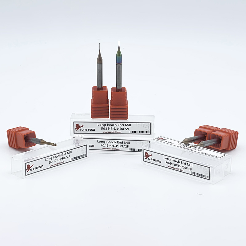
A long reach end mill features a short active cutting edge, known as the Length of Cut (LOC), paired with an extended, non-cutting shank. The cutting flutes only occupy the very tip of the tool. Immediately behind the flutes, the shank diameter is slightly reduced to provide clearance against the workpiece walls. This geometry allows the tool to drop deep into pockets without the non-cutting portion rubbing against the machined surfaces.
In machine shops, these tools go by several names. They are frequently referred to as reduced neck end mills, long-neck end mills, or relieved-shank end mills. Regardless of the terminology, the design intent remains identical: maximize reach while minimizing flute length. The transition from the fluted section to the neck usually features a smooth radius to prevent stress risers, which are common failure points under heavy radial loads.
The primary mechanical advantage of this design lies in its core strength. Flutes are essentially deep grooves ground into the carbide blank. By keeping the fluted section short, the un-fluted neck retains a much larger solid core diameter. This massive solid carbide section significantly increases the tool's moment of inertia. The tool gains immense resistance to bending forces, allowing for aggressive feed rates even when reaching deep into a mold cavity or aerospace structural component. You get the reach you need without sacrificing the rigidity required to push the tool hard.
Long length end mills take a completely different approach to deep-feature access. On these tools, the active cutting flutes extend continuously along the entire extended length of the tool. There is no reduced neck; the flutes run from the tip all the way up to the clamping shank. This provides a massive Long LOC, allowing the tool to engage tall vertical walls in a single axial pass.
However, this extended cutting capability introduces a severe primary mechanical disadvantage. The continuous fluting reduces the solid carbide core diameter across the entire extended length. Because the gullets remove so much structural mass, the tool becomes inherently flexible. This lack of core material makes the end mill highly prone to vibration and deflection under radial loads. Machining with these tools requires strict discipline regarding radial engagement limits to prevent the tool from bending away from the cut. If you push a fully fluted long tool too hard, it will snap at the collet face.
Understanding why one tool chatters violently while another cuts smoothly requires a look at the physics of machining. Tool deflection is the enemy of precision. When a tool bends during a cut, it creates a cascade of negative effects that ruin parts and destroy cutting edges. You cannot program your way out of bad physics; you must select the right geometry first.
The Length-to-Diameter (L/D) ratio is the most critical metric in extended tooling applications. It compares the unsupported length of the tool sticking out of the holder to its cutting diameter. In mechanical engineering, an end mill acts as a cantilever beam. According to cantilever beam physics, deflection scales exponentially based on these dimensions.
Deflection increases to the third power of the length (L⊃3;) and decreases to the fourth power of the diameter (D⁴). This means if you double the length of your tool stick-out, the tool becomes eight times more flexible. If you halve the core diameter, the tool becomes sixteen times more flexible. This mathematical reality explains why long length tools suffer disproportionately under high L/D ratios. A fully fluted long tool has both a long unsupported length and a small core diameter, creating a worst-case scenario for rigidity. In contrast, reduced neck geometries keep the core diameter as large as possible for as long as possible, fighting the L⊃3; penalty with a strong D⁴ advantage.
For example, consider a half-inch end mill sticking out three inches. If it is fully fluted, the core diameter might only be 0.250 inches. If it is a necked tool, the core diameter of the neck might be 0.480 inches. The difference in rigidity is massive, directly impacting how fast you can feed the tool without inducing chatter.
To truly grasp the rigidity difference, you must analyze how flute geometry removes structural mass. The gullet depth dictates how much room chips have to evacuate, but every thousandth of an inch of gullet depth removes solid carbide from the core. Tool manufacturers balance chip clearance with core strength, but long flutes always compromise the latter.
Consider the cross-sectional strength of a reduced neck versus a fluted section of the exact same outer diameter. If you slice a long length end mill in half, the cross-section looks like a star. The actual solid circle in the middle—the core—is quite small. If you slice through the neck of a long reach tool, the cross-section is a near-perfect, solid circle. Solid cylinders resist bending forces exponentially better than fluted shapes. Therefore, even if both tools have an overall reach of three inches and an outer diameter of half an inch, the tool with the solid neck will always handle higher radial cutting forces without bending.
When cutting forces overcome the tool's rigidity, the tool bends away from the material. As the flute exits the cut, the tension releases, and the tool snaps back. This rapid bending and snapping creates regenerative chatter. Tool deflection translates directly into this violent vibration, causing a visible wobble at the tool tip.
The compounding impact of tool vibration destroys machining outcomes. First, it ruins surface finish, leaving deep chatter marks and gouges on the workpiece walls. Second, it destroys dimensional accuracy, as the tool is physically pushed away from the programmed toolpath, leaving excess material behind. Third, the vibration generates excess heat due to inconsistent chip loads and rubbing. Finally, this erratic cutting action causes accelerated, premature edge wear. Carbide is incredibly hard but very brittle; the micro-impacts of chatter will quickly chip the cutting edges, forcing early tool replacement.
Selecting the right tool requires evaluating how each geometry performs across different machining metrics. You need to match the tool's physical characteristics to the specific demands of your part print.
Extended Tooling Performance Comparison
| Performance Metric | Long Reach (Reduced Neck) | Long Length (Fully Fluted) |
|---|---|---|
| Rigidity Profile | Higher (Solid core retains mass) | Lower (Fluted core removes mass) |
| Chatter Resistance | Excellent in deep pockets | Poor without strict parameter control |
| Tool Deflection Risk | Low to Moderate | High to Severe |
| Max Axial Depth (Ap) | Limited strictly to short LOC | Full extended length of the flutes |
| Chip Evacuation | Smooth flow around the neck | Prone to packing in long gullets |
Surface finish requirements often dictate tool selection in deep cavity work. Long reach tools provide superior bottom finishes in deep pockets. Because the solid neck minimizes wobble and vibration, the short cutting edges sweep the floor of the pocket cleanly. The tool remains stable, ensuring the floor is flat and free of chatter marks. You can often achieve a mirror finish on the floor of a pocket simply by keeping the tool rigid.
Conversely, long length tools carry a high risk of poor wall finish. When finishing a tall wall, the flexible nature of the long flutes makes the tool susceptible to harmonic vibrations. Unless radial engagement is strictly controlled and kept extremely light, the tool will leave witness marks and distinct chatter patterns along the vertical surfaces. Achieving a clean finish with a fully fluted long tool requires perfect feed and speed optimization, and often a spring pass to clean up deflection.
Getting chips out of a deep pocket is just as critical as cutting the material. If chips stay in the cutting zone, the tool recuts them. Recutting chips destroys the cutting edge and spikes the temperature inside the pocket. Heat is the primary killer of carbide coatings.
Long reach tools excel in this area. The neck clearance provides a wide-open pathway for chips to flow upward and out of the cavity. This easier chip evacuation reduces recutting and prevents heat buildup, extending tool life. You can often run these tools with standard flood coolant or a moderate air blast.
Long length tools struggle with chip evacuation in enclosed spaces. The long flutes can trap chips within the deep, enclosed slots. The chips pack into the long gullets, leading to immediate tool breakage if not managed. Running these tools in deep pockets requires high-pressure coolant or strong air blasts directed perfectly into the cutting zone to blast the chips up the flutes and out of the part.
Knowing the mechanics is only half the battle; applying that knowledge to your daily setups is where you gain efficiency. Use this framework to determine which tool geometry matches your specific machining operation.
You should default to long reach end mills whenever your operation requires deep access but does not require deep axial cutting. Deep pocketing where only the floor or bottom corners require machining is the perfect use case. The tool drops into the pocket, machines the floor with its short flutes, and the relieved neck safely clears the upper walls.
These tools are also essential for reaching past obstructions in 3+2 or simultaneous 5-axis setups. When the spindle head must tilt closely to a fixture, the extended neck provides the necessary physical clearance without sacrificing rigidity. You can machine complex aerospace brackets without colliding with the trunnion table.
Rest machining and deep cavity roughing also benefit from this geometry. As long as the programmed axial depth of cut (Ap) remains shallower than the tool's LOC, you can rough out deep cavities efficiently. Furthermore, in micro-machining applications, utilizing long-neck micro end mills is the only viable way to access miniature, deep features. A fully fluted micro tool would snap instantly under any radial load, whereas the necked version provides just enough core strength to survive the operation.
Long length end mills are highly specialized tools that should be reserved for specific operations where a reduced neck tool physically cannot perform the job. Their primary application is finishing tall, continuous vertical walls without leaving step-down witness marks. If a part requires a perfectly seamless 3-inch vertical wall, stepping down with a short-flute tool will leave faint lines at every depth increment. A long length tool can finish the entire wall in one smooth, continuous axial pass.
They are also required for deep peripheral profiling where the entire side of the part must be machined simultaneously. Additionally, these tools perform well when machining low-density materials like tooling foams, plastics, and certain soft aluminums. In these materials, the cutting forces are minimal, meaning the deflection risks associated with the flexible core are drastically reduced. You can utilize the full flute length without inducing severe chatter.
Even the correct tool will fail if driven by the wrong toolpath. Extended tooling requires a complete departure from standard milling parameters. You must adjust your programming approach to account for the physical limitations of high L/D ratios.
When a long tool starts screaming and chattering, the common machinist instinct is to drastically drop the RPM and feed rates. This is known as the slow down trap. While slowing down might temporarily quiet the chatter, it often leads to tool rubbing. The tool stops shearing the material and starts pushing it. This generates massive friction, excess heat, and causes premature edge failure rather than proper chip formation.
Instead of guessing, you must rely on manufacturer cutting data. It is an absolute necessity to consult tooling manufacturer specifications for Surface Footage (SFM) and Inch Per Tooth (IPT). These numbers are specifically calibrated for extended LOC tools and specific materials. The parameters for cutting soft 1018 steel will differ wildly from those used on hardened aerospace alloys.
Furthermore, traditional slotting is catastrophic for high L/D ratio tools. Burying a long tool 180 degrees into the material maximizes radial forces and guarantees severe deflection or instant breakage. Never slot with extended tooling. Always use dynamic milling techniques to control the engagement angle.
Common Toolpath Adjustments for Extended Reach
| Machining Variable | Standard Tooling | Extended Tooling Adjustment |
|---|---|---|
| Radial Engagement (Ae) | Up to 50% of tool diameter | Limit to 5% - 10% of tool diameter |
| Feed per Tooth (IPT) | Standard catalog spec | Increase slightly to stabilize tool pressure |
| Spindle Speed (RPM) | Standard catalog spec | Adjust up or down 10% to break harmonics |
| Entry Method | Plunge or steep ramp | Shallow helical entry only |
Modern CAM software provides the ultimate solution for managing tool deflection. Utilizing High-Efficiency Milling (HEM) or trochoidal toolpaths is mandatory for extended tools. HEM combines a high axial depth of cut (Ap) with a very low radial engagement (Ae).
Taking a tiny radial bite thins the chip and directs the cutting forces axially up into the spindle rather than radially against the side of the tool. Spindles have massive axial bearings; they can handle upward pressure easily. By shifting the force vector, HEM allows long tools to cut aggressively without bending.
When programming these toolpaths, follow these specific steps to ensure success:
Extended tools act as massive levers, magnifying any inaccuracies in your machine spindle or tool holder. Spindle runout, measured as Total Indicator Reading (TIR), is the amount the tool wobbles off its true centerline. If your holder has 0.0005 inches of runout at the collet face, an extended tool sticking out four inches might have 0.003 inches of runout at the cutting tip.
This magnified runout means only one flute is doing all the cutting, leading to instant chatter and rapid tool death. Therefore, utilizing high-precision tool holders is a strict requirement. Shrink fit holders, hydraulic chucks, or ultra-high-precision milling chucks must be used when running either long reach or long length geometries. Standard ER collets often lack the gripping force and concentricity required to prevent runout-induced chatter at extended lengths.
A: LOC is the fluted, active cutting portion of the tool. Reach is the total distance from the tool holder to the tip, which may include a non-cutting reduced neck. Reach dictates how deep the tool can go, while LOC dictates how much material can be engaged axially in a single pass.
A: Use them for deep pocketing, reaching past part obstructions, micro-machining deep cavities, or any application where you need extended reach but only require a shallow depth of cut. They provide superior rigidity because the un-fluted neck retains a larger, stronger solid carbide core.
A: Avoid the instinct to just slow down the machine. Instead, reduce radial engagement (Ae), utilize chip thinning strategies, lower the spindle speed specifically to break harmonics, increase feed per tooth slightly to stabilize the tool, and ensure runout is minimized in the tool holder.
A: Continuous flutes reduce the solid core diameter of the tool. Combined with a high Length-to-Diameter (L/D) ratio, radial cutting forces easily bend the flexible core, leading to wobble, poor finish, and rapid tool wear. The lack of solid mass makes it inherently weak against side loads.
A: Yes, provided it is center-cutting, but ramping or helical interpolation is highly recommended to reduce axial pressure and evacuate chips efficiently from deep cavities. Plunging straight down traps chips and increases heat, which can quickly destroy the cutting edge on extended tools.