- All
- Product Name
- Product Keyword
- Product Model
- Product Summary
- Product Description
- Multi Field Search

Views: 0 Author: Site Editor Publish Time: 2026-08-06 Origin: Site

Producing consistent, burr-free edge radii is a daily challenge on the shop floor. Machinists constantly balance part quality against production efficiency. Relying on 3D profiling with ball end mills eats up machine hours and inflates cycle times. On the other hand, manual deburring introduces human error, inconsistent edge breaks, and scrapped parts. When structural integrity and handling safety are print requirements, improper edge-finishing methods destroy profit margins through rejected components and excessive secondary operations.
To fix this, shops use dedicated form tools engineered specifically for edge profiling. Integrating corner rounding end mills into the primary machining cycle eliminates manual finishing and simplifies CAM programming. This technical guide breaks down how to select, apply, and optimize these specialized tools to achieve perfect external radii across various machining setups.
Industry terminology often causes confusion, leading to incorrect tool ordering and scrapped setups. Knowing the exact tool geometry prevents these errors. The difference between a corner rounding tool and a bull nose tool comes down to where you place the machined radius.
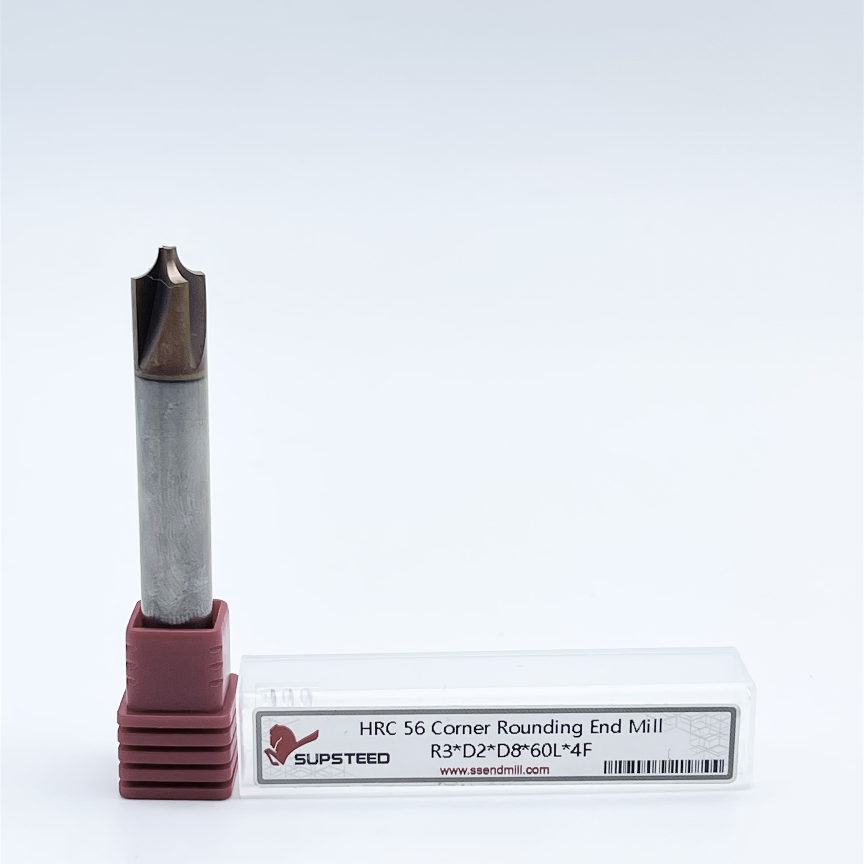
Corner rounding end mills are dedicated form tools with a concave cutting edge. You use them exclusively to machine a convex radius on the outside edge of a workpiece. The tool wraps around the external corner, shearing away the sharp 90-degree intersection to leave a smooth profile. We typically run these along the periphery of a part using a standard 2D contour toolpath.
In contrast, bull nose end mills—often called corner radius end mills—have a flat bottom with a slight convex radius ground into the cutting tip. You use bull nose tools to mill flat pockets that need a concave fillet on the inside corner where the floor meets the wall. A bull nose tool cannot round an outside edge in a single pass. A corner rounding tool cannot mill a flat pocket floor.
Tool Terminology Comparison
| Tool Type | Cutting Edge Geometry | Machined Feature | Primary Application |
|---|---|---|---|
| Corner Rounding End Mill | Concave | Convex (Outside Radius) | External edge breaking, structural fillets, aesthetic rounding |
| Bull Nose / Corner Radius End Mill | Convex (on tip) | Concave (Inside Fillet) | Pocket milling, floor-to-wall fillets, 3D roughing |
Sharp machined edges are safety hazards during assembly and act as starting points for micro-fractures. Operators can break edges using manual files, but manual methods lack repeatability. Medical device and aerospace prints strictly dimension edge-break tolerances. A manual file cannot guarantee a true 0.015-inch radius across a complex titanium bracket.
Using small-radius form tools replaces manual deburring with a controlled CNC operation. The tool executes a precise 2D contour around the part perimeter. It shears away burrs and leaves a dimensionally accurate edge break. This guarantees every part matches the print exactly, eliminating the scrap risk of heavy-handed manual deburring.
Sharp external corners create massive stress concentrations in load-bearing components. When a part flexes, these sharp intersections become failure points. Removing the sharp edge and replacing it with a continuous structural fillet distributes mechanical stress over a wider area. This enhances the overall strength and fatigue life of the component.
A single-pass form tool ensures this radius is perfectly continuous. If you attempt to create this structural fillet using multi-pass interpolation with a flat end mill, the surface will contain microscopic steps. These facets act as miniature stress risers. A dedicated form tool cuts the entire curve simultaneously, leaving a structurally sound surface.
Visible components in automotive interiors and consumer electronics require flawless aesthetic finishes. The tactile feel of a product dictates its perceived quality. Machining these parts requires blending the edge radius perfectly with the adjacent flat top and side walls.
Achieving this seamless blend is difficult. If you set the tool too deep, it leaves a distinct step or witness mark on the top surface. If set too shallow, it leaves an incomplete curve. Form tools designed for edge rounding allow programmers to dial in exact radial and axial offsets. This ensures the machined curve transitions invisibly into the flat surfaces.
High-volume production environments quickly expose the limitations of High-Speed Steel (HSS) and Cobalt tooling. Form tools experience high tool pressure because a large surface area of the cutting edge engages the material simultaneously. This continuous engagement generates immense heat and friction, rapidly degrading HSS cutting edges.
Implementing carbide corner rounding end mills provides superior abrasion resistance and thermal stability. Solid carbide maintains its hardness at significantly higher cutting temperatures. Premium carbide tools feature precision-ground cutting tips and reinforced flute geometries that strengthen the tool end. This geometric reinforcement prevents the micro-chipping that frequently destroys HSS tools during heavy cuts in alloy steels.
The return on investment for carbide tooling becomes obvious when analyzing machine uptime. The extended tool life drastically reduces the frequency of tool changes. Fewer tool changes mean less machine downtime, fewer offset adjustments, and a stable production run.
Tool deflection destroys surface finish and dimensional accuracy. Because corner rounding tools push a large concave profile into the workpiece, they generate significant radial cutting forces. These forces actively push the tool away from the part.
Carbide possesses an inherent stiffness—a modulus of elasticity nearly three times that of steel. This extreme rigidity allows the tool to resist radial forces without deflecting. Minimizing deflection ensures the machined radius matches the programmed toolpath exactly. A rigid tool eliminates the harmonic vibrations that cause chatter marks on the finished radius.
Selecting the correct physical vapor deposition (PVD) coating maximizes the performance of the carbide substrate. The coating must match the thermal and chemical properties of the workpiece material.
Common Coating Applications
| Coating Type | Primary Materials | Key Machining Benefit |
|---|---|---|
| Titanium Aluminum Nitride (TiAlN) | High-temp alloys, stainless steels, tool steels | Forms an aluminum oxide layer under high heat, shielding carbide from thermal shock. |
| Zirconium Nitride (ZrN) | Aluminum, brass, copper | Provides a low coefficient of friction, preventing gummy materials from welding to the edge. |
| Uncoated / Polished Flutes | Plastics, soft aluminum alloys | Maintains a razor-sharp shearing edge where heat resistance is less critical than sharpness. |
Tool selection begins with the engineering print. You must match the tool's ground radius directly to the print specifications. Manufacturers offer these tools in standard fractional and metric sizes, ranging from micro-radii for precision medical parts to massive profiles for heavy equipment components.
Beyond the nominal size, evaluate the tool's stated profile tolerance. High-performance aerospace applications often require the radius to hold a tolerance of +/- 0.001 inches. Standard commercial-grade tools may only hold +/- 0.003 inches. Specifying a tool with a tighter profile tolerance than the print requires wastes money, while under-specifying leads to part rejection.
Flute count dictates chip evacuation capacity and surface finish quality. Choosing the wrong flute count leads to chip packing, tool breakage, or unacceptable chatter.
The physical geometry of the tool tip dictates how you apply it to the workpiece.
Calculating correct spindle speeds for form tools presents a unique technical challenge known as the effective diameter problem. The cutting speed, measured in Surface Feet per Minute (SFM), varies continuously along the curve of the concave radius. The tool spins fastest at its major diameter (the widest part of the tool) and slowest at its minor diameter (the narrow tip).
If a programmer calculates the RPM based on the tool's major diameter, the actual cutting speed at the point of material engagement will be far too low. This low SFM causes the tool to rub rather than shear the material, generating massive heat, poor surface finish, and severe chatter. Programmers must calculate the RPM based on the effective cutting diameter—the specific point on the radius where the heaviest cutting action occurs. This ensures the cutting edge maintains enough velocity to cleanly shear the chip.
For example, if you are using a 1/2-inch major diameter tool to cut a 1/8-inch radius, the effective diameter at the midpoint of the cut is significantly smaller than 1/2 inch. Using the full 1/2-inch diameter for your math will result in an RPM that drags the tool through the cut. Always use the manufacturer's effective diameter charts when setting your baseline speeds.
Catastrophic tool breakage frequently occurs when programmers ignore the tool's minor diameter. The minor diameter is the flat, non-cutting dimension at the very tip of the tool, just below where the radius begins. When profiling the top edge of a part, this minor diameter drops below the top surface and runs parallel to the vertical side wall.
If the part features a stepped shoulder, or if the workholding fixture sits too close to the machined edge, the non-cutting minor diameter will crash into the obstruction. Machinists must verify that the minor diameter has adequate clearance from all adjacent vertical walls, steps, and vise jaws to prevent unwanted rubbing, friction welding, or immediate tool snapping.
The reality of machining a perfect radius is dealing with witness marks. These are the faint, visible lines left where the machined radius meets the flat top or side of the part. These marks occur due to microscopic runout in the tool holder or slight inaccuracies in the machine's Z-axis calibration.
Mitigating these marks requires precision setup strategies. Programmers often dial in the tool offsets, intentionally leaving a micro-step of 0.001 inches for a final, light finishing pass. Alternatively, tooling manufacturers design specific end mills with a slight flare or blend angle (typically 1 to 5 degrees) at the top of the radius. This flare allows the tool to sweep smoothly into the flat surface, feathering the cut and completely eliminating the harsh witness mark.
When programming the 2D contour, machinists must also consider the lead-in and lead-out moves. Plunging directly down in the Z-axis or feeding straight into the part in the X/Y axes will leave a dwell mark and potentially chip the tool tip. Always program an arc lead-in and arc lead-out. Rolling into the cut with a smooth radial move allows the cutting pressure to build gradually. This protects the fragile minor diameter of the tool and ensures a seamless transition where the toolpath starts and stops.
Form tools demand absolute rigidity. Because they cut a wide swath of material simultaneously, they generate forces that attempt to pull the part out of the vise or push the tool up into the spindle. A loose setup guarantees chatter and dimensional failure.
Machinists must utilize rigid tool holders to combat these forces. Shrink fit holders or hydraulic chucks provide 360-degree gripping force on the tool shank, minimizing runout and preventing the tool from pulling out during heavy cuts. Similarly, the workholding must be robust. Standard machinist vises with aluminum soft jaws work well, provided the jaws are milled to match the part profile exactly. However, for thin-walled parts, vacuum chucks or custom fixture plates with edge clamps offer superior vibration dampening. If the part rings or chatters when tapped with a dead-blow hammer during setup, it will chatter when the form tool engages.
Troubleshooting Common Edge Profiling Defects
| Machining Defect | Potential Cause | Corrective Action |
|---|---|---|
| Heavy Chatter / Vibration | Insufficient setup rigidity or excessive RPM based on major diameter. | Switch to a shrink fit tool holder. Recalculate RPM using the effective cutting diameter. |
| Visible Witness Marks | Z-axis offset mismatch or tool runout. | Adjust Z-axis offset by 0.001 inches. Use a tool with a 5-degree blend angle. |
| Premature Edge Chipping | Feed rate too high or recutting chips in the cut zone. | Reduce feed per tooth (IPT). Increase coolant pressure to flush chips from the flute valleys. |
| Galling / Built-Up Edge | Incorrect coating for the material (e.g., using TiAlN on soft aluminum). | Switch to a ZrN coated or uncoated polished flute tool for non-ferrous materials. |
When analyzing production efficiency, the comparison between a dedicated form tool and a 3D surfacing operation is stark. Creating an external radius using a ball end mill requires a 3D CAM toolpath with hundreds of tiny step-downs. The machine must interpolate the X, Y, and Z axes simultaneously, taking light passes to gradually form the curve. This process takes minutes per part and requires complex CAM programming to ensure the step-over distance yields an acceptable surface finish.
A dedicated corner rounding end mill completes the exact same feature in a single, rapid 2D contour pass. The CAM programming takes seconds—simply select the edge and apply a 2D profile toolpath. The machine executes the cut in a fraction of the time.
To put this into perspective, consider a standard 6061 aluminum aerospace bracket requiring a 0.125-inch radius along a 20-inch continuous outer perimeter. Programming a 1/4-inch ball end mill to surface this radius with a 0.005-inch step-over requires 25 passes. Even at high feed rates, this surfacing operation can easily consume three to four minutes of cycle time per part. Switching to a dedicated 0.125-inch radius form tool reduces this to a single contour pass. Running at 100 inches per minute, the tool completes the entire 20-inch perimeter in exactly 12 seconds. Over a production run of 1,000 parts, this single tooling change saves over 50 hours of machine time.
The hidden costs of manufacturing often reside in the deburring department. Manual deburring requires dedicated labor, increases the overall lead time, and introduces a high degree of variability. If an operator slips with a deburring tool, a completely machined, expensive component becomes scrap.
Integrating the edge rounding process directly into the primary CNC cycle eliminates these secondary operations entirely. The part comes off the machine completely finished, inspected, and ready for assembly or shipping. By quantifying the labor savings, the reduction in scrap rate, and the increase in throughput, shops can easily justify the higher initial cost of premium carbide form tools. The result is a significantly lower cost-per-part and a more predictable manufacturing workflow.
A: A corner rounding end mill features a concave cutting edge designed to cut convex radii on the outside external edges of a part. A corner radius (or bull-nose) end mill features a flat bottom with a convex radius on the tips, used to cut concave inside fillets along the floor of a pocket.
A: No. The vast majority of these tools are not center-cutting. They are designed strictly for peripheral milling along an external edge. Plunging directly into solid material will crush the non-cutting tip and instantly break the tool.
A: Solid carbide provides superior rigidity, extreme heat resistance, and extended wear life. This inherent stiffness prevents tool deflection and chatter, reduces edge micro-chipping, and maintains the precise profile tolerance far longer than HSS during high-volume production.
A: You must calculate the RPM based on the tool's effective cutting diameter, not the major maximum diameter. The effective diameter is the specific point on the radius curve where the heaviest cutting occurs. Using the major diameter results in an SFM that is too slow, causing rubbing.
A: Witness marks occur when the machined radius does not perfectly blend with the adjacent flat surface. This is typically caused by microscopic tool runout, incorrect Z-axis depth offsets, or a lack of setup rigidity causing the tool to deflect away from the programmed path.
A: Climb milling is heavily preferred for corner rounding operations. Climb milling directs the cutting forces down into the workpiece and fixture, improving rigidity, enhancing surface finish, and extending tool life by ensuring the cutting edge shears the material cleanly rather than rubbing.