- All
- Product Name
- Product Keyword
- Product Model
- Product Summary
- Product Description
- Multi Field Search

Views: 0 Author: Site Editor Publish Time: 2026-08-14 Origin: Site
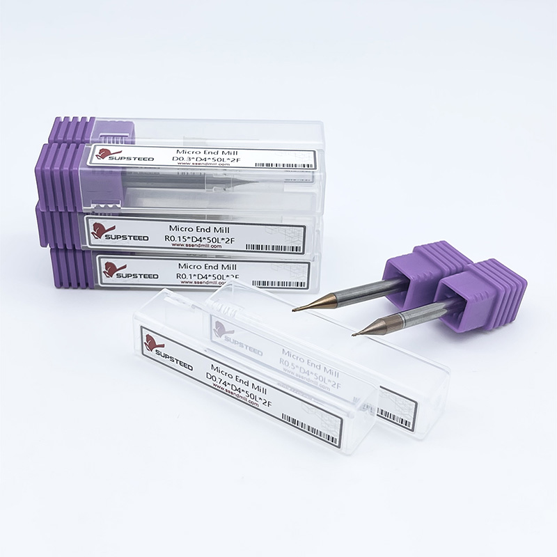
The demand for extreme miniaturization is accelerating across medical, aerospace, and micro-electronics manufacturing. Precision requirements now scale down to features smaller than a human hair. Standard macro-machining tools hit hard physical limitations when generating sub-2mm features. Attempting to scale down conventional milling operations introduces severe manufacturing challenges. Standard tools suffer from catastrophic deflection under lateral loads, exhibit poor chip evacuation in tight spaces, and experience unacceptable runout at microscopic scales. These failures lead to high scrap rates and excessive tool breakage, disrupting production timelines and ruining expensive workpiece materials. Engineers solve these tight-tolerance challenges using micro end mills. These highly specialized cutters provide the exact geometry and rigidity needed for microscopic feature generation. We will outline specific micro-machining applications, evaluate tooling geometries like carbide micro end mills, and provide a practical framework for mitigating implementation risks on the shop floor.
Micro tooling operates in a completely different dimensional reality than conventional machining. The standard cutting diameter for these tools typically ranges from 0.005 inches to 0.125 inches. In metric terms, this spans from 0.1mm up to 2mm. Operating at this scale requires a fundamental shift in how operators approach cutting dynamics. You cannot simply shrink a half-inch end mill and expect it to cut effectively. The core-to-diameter ratio changes drastically to accommodate the physical limits of the material.
Macro tools might utilize a 50% core diameter to maximize flute space for large chips. Micro tools often require a 60% to 70% core diameter. This thicker web provides the structural integrity needed to survive lateral cutting forces. Machinists must carefully balance this increased core strength against the reduced space available for chip clearance. Furthermore, the relief angles on micro tools are ground with extreme precision to prevent the heel of the tool from rubbing against the workpiece, which would instantly generate enough heat to snap the cutter.
High-Speed Steel (HSS) is entirely non-viable at the micro scale. HSS lacks the inherent stiffness required to maintain dimensional accuracy when cutting diameters drop below 2mm. If you attempt to run an HSS tool at 0.5mm, the tool will simply bend, rub against the workpiece, and snap before it ever shears a chip.
The physics of micro-machining demand superior material properties. We rely on the high Young’s Modulus of sub-micron grain solid carbide. This material provides exceptional stiffness. It actively resists deflection under the lateral cutting forces generated during micro-slotting or profiling. When a tool resists deflection, it maintains the programmed tool path and ensures tight tolerances. Deflection is the enemy of micro-machining; even a few tenths of a thousandth of an inch of flex will ruin a micro-fluidic channel or a medical implant feature.
Carbide grain size directly impacts performance on the shop floor. Sub-micron and ultra-fine grain structures allow tool manufacturers to grind incredibly sharp cutting edges. These sharp edges shear material cleanly rather than plowing through it. Fine grain structures also prevent micro-chipping along the cutting edge. A chipped edge on a macro tool might just leave a poor surface finish. A chipped edge on a micro tool changes the cutting dynamics entirely, leading to immediate catastrophic failure.
Micro end mills execute highly specific geometric operations that larger tools cannot physically perform. Machinists rely on these cutters for several distinct processes:
These tools shape a remarkably broad spectrum of materials. You will find them cutting traditional metals like aluminum and brass. They are equally effective in advanced composites, engineered plastics like PEEK, and specialized alloys. The cutting mechanics remain consistent across these materials, though feed rates, spindle speeds, and tool geometries vary wildly depending on the substrate.
The medical sector relies heavily on micro-machining. Manufacturers constantly machine biocompatible materials such as surgical-grade Titanium (Ti-6Al-4V), PEEK, and 316L stainless steel. These materials are notoriously difficult to cut. Titanium tends to gall and weld to the cutting edge, while 316L work-hardens rapidly if the tool rubs instead of cutting.
Common applications include machining bone plates, intricate surgical instruments, and micro-screws. Cardiovascular stents require microscopic lattice structures. These components demand absolutely burr-free finishes. Even a microscopic burr can cause tissue damage or harbor bacteria inside the human body. Micro cutters shear the material cleanly, eliminating the need for secondary deburring operations that could alter the dimensional accuracy of the part.
Heat management in modern electronics requires intricate physical structures. Machinists use micro cutters to profile copper heat sinks and create micro-channels for liquid cooling systems. Precision test sockets for semiconductor manufacturing also require thousands of microscopic holes and slots.
This industry demands extreme surface finishes and flawless dimensional accuracy. Tools must cut cleanly through copper, aluminum alloys, and specialized electronic composites like FR4. Copper is particularly gummy and prone to smearing. If a micro tool is not sharp enough, it will push the copper rather than cut it, leaving a rolled burr. Delamination or smearing in these materials ruins the electronic properties of the final component. Sharp, rigid micro tools prevent these defects.
Aerospace engineering increasingly utilizes micro-fluidic channels for thermal management and fuel delivery. Micro cutters generate fuel metering valves and delicate sensor housings. These components monitor flight data and must perform flawlessly under extreme pressure and temperature variations.
The primary challenge here involves the workpiece material. Aerospace components often utilize high-temperature alloys like Inconel and Hastelloy. Machining these superalloys at micro scales generates intense localized heat. Advanced aerospace polymers also present challenges, as they can melt if the cutting edge rubs. Success requires highly optimized tool geometries, strict adherence to calculated feed rates, and rigid machine setups to prevent work hardening.
Mold makers use micro ball end mills and square end mills for fine detailing. They generate complex 3D contours and engrave intricate logos directly into hardened tool steels (often 45 to 65 HRC). The ability to machine these features directly into hard metal is a significant technological leap for the tooling industry.
Historically, generating microscopic mold features required Electrical Discharge Machining (EDM). EDM is accurate but incredibly slow. It also requires the creation of custom copper or graphite electrodes for every unique feature. Using micro cutters reduces the need for secondary EDM processes. This direct-milling approach drastically shortens lead times, eliminates the electrode manufacturing step, and streamlines overall mold production.
Selecting the correct flute count is a primary decision at the micro level. Engineers constantly evaluate the trade-off between 2-flute and 4-flute designs. The physical space available for chip evacuation shrinks exponentially as tool diameter decreases. If chips cannot escape the cutting zone, they will be re-cut by the tool. Re-cutting causes immediate friction spikes and instantaneous tool breakage.
A 2-flute design offers superior chip clearance. This open geometry is absolutely critical when machining softer materials, aluminum, and plastics. These materials generate larger, stringier chips that need room to evacuate. Conversely, a 4-flute design provides a thicker core and higher strength. It yields a better surface finish in harder materials like steel and titanium, provided the chips are small enough to evacuate. In hard milling, the chips are typically tiny and brittle, making a 4-flute tool highly effective.
Flute Count Selection Guide
| Flute Count | Primary Advantage | Primary Disadvantage | Ideal Materials |
|---|---|---|---|
| 2-Flute | Maximum chip clearance volume | Lower core strength, more prone to deflection | Aluminum, Plastics, Brass, Copper |
| 3-Flute | Excellent balance of strength and clearance | Can be harder to program exact chip loads | Non-ferrous alloys, mild steels |
| 4-Flute | Maximum core strength, superior surface finish | Minimal chip clearance, high risk of packing | Hardened steels, Titanium, Inconel |
Coatings play a vital role in reducing friction and managing thermal loads. Common micro tool coatings include AlTiN, TiCN, and various Diamond-like carbon applications. These layers protect the carbide substrate from abrasive wear and heat degradation, extending the life of the tool significantly in abrasive environments.
However, coating micro tools carries a specific risk. Standard physical vapor deposition (PVD) coatings add measurable thickness to the tool. A 2-micron coating layer might be negligible on a half-inch tool. On a 0.2mm tool, that same coating thickness significantly dulls the cutting edge. When machining sticky materials or using tools under 0.5mm, engineers often opt for uncoated, highly polished carbide to maintain maximum edge sharpness. A dull micro tool will rub, generate heat, and break.
Tool Coating Application Guide
| Coating Type | Primary Benefit | Ideal Workpiece Material | Micro-Machining Consideration |
|---|---|---|---|
| AlTiN | High heat resistance | Steels, Titanium, Inconel | Requires high speeds to activate aluminum oxide layer. |
| TiCN | High hardness and lubricity | Cast iron, abrasive alloys | Good for general purpose, but watch for edge rounding. |
| Amorphous Diamond | Extreme wear resistance | Graphite, composites, ceramics | Excellent for abrasive non-ferrous materials. |
| Uncoated (Polished) | Maximum edge sharpness | Aluminum, plastics, brass | Best for sub-0.5mm tools to prevent coating-induced dulling. |
Feature depth dictates the required tool reach. Engineers must evaluate standard versus long-reach or stub-flute designs. Using a tool with flutes longer than necessary severely compromises rigidity. The longer the fluted section, the weaker the tool becomes.
A reduced neck diameter allows the tool to reach deep into pockets without the shank rubbing against the workpiece walls. A stub-flute design concentrates the cutting action at the very tip while maintaining a thick, un-fluted neck for maximum possible tool rigidity. This geometry prevents shank interference in deep pocketing while minimizing deflection. Whenever possible, machinists should select the shortest overall length and the shortest flute length that can physically complete the cut.
Standard runout tolerances are catastrophic for micro tools. Total Indicator Runout (TIR) measures how far a tool wobbles off its true axis of rotation. A runout of 0.0005 inches is highly acceptable for standard machining with a half-inch end mill.
Apply that same 0.0005-inch runout to a 0.010-inch micro tool, and the cutting dynamics fail completely. The runout effectively halves the chip load on one flute and doubles it on the opposite flute. The tool experiences massive, uneven lateral force. It will snap almost instantly upon entering the material. Mitigation requires high-precision tool holding. Standard ER collets are generally insufficient for true micro-machining. Machinists must utilize shrink-fit holders or high-end hydraulic chucks to keep TIR below 0.0001 inches. Measuring runout dynamically at the tool tip before hitting cycle start is a mandatory step.
Achieving the recommended Surface Feet per Minute (SFM) is a major hurdle. Because the tool circumference is so small, you must spin it incredibly fast to achieve proper cutting speeds. Micro tools often require spindles capable of 30,000 to 80,000 RPM or higher. Running a 0.2mm tool at 10,000 RPM simply will not generate enough surface speed to shear the material cleanly.
If you lack spindle speed, you must carefully adjust your feed rates. The goal is to maintain a minimum chip thickness. If you feed the tool too slowly, the cutting edge will rub against the material instead of shearing it. Rubbing generates immense heat, work-hardens the material, and causes rapid edge wear. Engineers must calculate feed per tooth meticulously to ensure the tool stays engaged in the cut. Radial chip thinning calculations are absolutely necessary when taking light step-overs.
Steps for Dialing in Micro Feeds and Speeds:
Standard flood coolant introduces severe risks at micro scales. The physical viscosity of heavy coolant fluids can actually push a fragile micro tool off its programmed path, causing deflection and dimensional inaccuracy. Furthermore, intermittent cutting with flood coolant causes thermal shock, leading to micro-cracks in the carbide substrate.
Flood coolant also struggles to flush microscopic chips out of deep slots. The fluid simply pools in the cavity, trapping the chips. Instead, modern micro-machining strongly prefers high-pressure air blast or Minimum Quantity Lubrication (MQL). A targeted air blast clears micro-chips effectively without introducing thermal shock. MQL provides just enough lubricity to prevent built-up edge (BUE) without drowning the cutting zone. The air stream must be precisely aimed directly at the tool tip; even a slight misalignment will result in chip packing and tool failure.
Evaluating production efficiency requires looking beyond the initial purchase price of the cutter. Cheaper micro tools often suffer from inconsistent edge prep and poor concentricity. This leads to unpredictable breakage during long machining cycles. In micro-machining, predictability is far more valuable than a low upfront tool cost.
Unpredictable breakage results in high scrap rates. Ruining a complex aerospace component during the final micro-engraving pass destroys thousands of dollars in material and labor. Machine downtime spent extracting broken micro tools further damages profitability. Investing in application-specific micro geometries yields higher returns in production environments. High-quality tools offer predictable wear patterns, allowing operators to swap them out before catastrophic failure occurs. Establishing a strict tool life management protocol based on cutting time or linear distance traveled prevents unexpected scrap.
Utilizing micro cutters effectively requires assessing hidden operational demands. You cannot run a high-precision micro cutter on a loose, aging machine. The setup requires absolute rigidity. Any vibration in the machine casting transfers directly to the tool tip, causing immediate failure. The spindle bearings must be in pristine condition to support high RPMs without inducing chatter.
Thermal stability is equally important. As a machine warms up, the spindle and casting grow. A thermal growth of 0.001 inches will completely wipe out a micro-machined feature. High-end micro-machining centers utilize chiller units to maintain a constant spindle temperature. Furthermore, the CNC controller must process data rapidly. Advanced controllers need high-speed look-ahead blocks to process complex 3D micro-paths. If the controller lags, the machine stutters. Stuttering causes the tool to dwell in one spot, generating heat, work-hardening the material, and snapping the cutter.
Success in micro-machining requires strict adherence to mechanical principles and precise setup procedures. Operators must control runout, manage chip evacuation, and maintain rigid machine environments to prevent tool failure.
A: A micro end mill is a specialized cutting tool with a cutting diameter typically ranging from 0.1mm up to 2mm (0.005 to 0.078 inches). Manufacturers engineer these tools specifically for precision feature generation, micro-slotting, and tight-tolerance contouring in miniature components.
A: Carbide provides the extreme rigidity and high Young's Modulus necessary to survive micro-machining. HSS lacks the stiffness required at microscopic diameters and will deflect, bend, or break under lateral cutting forces. Sub-micron grain carbide maintains a sharp edge and resists deflection.
A: Preventing breakage requires controlling three main factors. First, minimize spindle runout (TIR) using high-precision tool holders. Second, ensure proper chip evacuation using high-pressure air blast or MQL. Third, maintain accurate chip loads to prevent the tool from rubbing and generating excess heat.
A: Because of their extremely small circumference, micro cutters require very high spindle speeds to achieve the correct surface speed (SFM) for cutting. Spindle speeds ranging from 30,000 to over 100,000 RPM are frequently required to optimize cutting dynamics and prevent tool dragging.
A: Yes, they can effectively cut hardened steel. Success requires tools made from sub-micron grain solid carbide, appropriate heat-resistant coatings like AlTiN, and a highly rigid machine setup. Operators must also utilize precise, shallow depth-of-cut strategies to manage tool load.
A: Micro end mills feature specific flute geometries designed for side milling, slotting, and plunging with flat or ball profiles. Engraving tools typically feature a single-flute V-shape design. Engravers are meant specifically for scoring or marking surfaces, not for clearing pockets or profiling walls.