Please Choose Your Language
- All
- Product Name
- Product Keyword
- Product Model
- Product Summary
- Product Description
- Multi Field Search

Views: 0 Author: Site Editor Publish Time: 2026-09-20 Origin: Site

Getting consistent results in extreme length-to-diameter ratio machining takes more than simply buying expensive equipment. You need meticulous execution right at the machine spindle. We are currently seeing a massive industry shift toward lights-out manufacturing and fully automated machining cells. Aerospace, automotive, and medical sectors are demanding deeper, smaller-diameter holes in increasingly difficult-to-machine superalloys. In these unattended environments, unpredictable tool failure is no longer just an inconvenience. It is a critical bottleneck that ruins expensive parts.
Consequently, modern shops are abandoning trial-and-error setups. They rely instead on empirical, data-driven strategies to stabilize the cutting environment and manage chip evacuation. Implementing these proven methodologies will drastically reduce thermal accumulation, control chip formation, and significantly extend the lifespan of your deep hole drilling tools.
The entry phase of a deep bore is undoubtedly the most vulnerable point of the entire operation. Imagine guiding a drill that is twenty times longer than its diameter into a raw metal billet. Without a rigid starting point, the initial thrust forces cause the unsupported tip to skate across the flat surface. This phenomenon is known as tool walking. It instantly compromises the straightness of the bore and places asymmetric, destructive stress on the tool margins.
To counteract this mechanical vulnerability, machining a highly accurate pilot hole is an absolute prerequisite. A pilot hole acts as a custom-fit, rigid guide bushing cut directly into the workpiece. Standard engineering practice dictates drilling this initial guide to a depth of one and a half to two times the diameter.
Specifically, the geometry of the pilot drill must perfectly complement the longer tool that follows it. The point angle of the pilot drill should be equal to, or slightly flatter than, the point angle of the deep-hole tool. For instance, if your main tool has a 140-degree point angle, the pilot should match it. Furthermore, the diameter of the pilot should be nominally larger, often by just a few ten-thousandths of an inch. If the pilot hole features a narrower point angle, the subsequent drill will crash into the material at its fragile outer corners first. This leads to immediate edge chipping and catastrophic failure.
Traditional shallow drilling often utilizes a constant spindle speed and feed rate from the moment the tool enters the cut until it retracts. In deep hole applications, adopting this static approach is highly destructive. Managing the transition of a long, slender tool into the pilot bore requires a carefully programmed adjustment of cutting parameters.
When the long drill first enters the pilot hole, the spindle speed should be drastically reduced to approximately ten to fifteen percent of the final operating speed, paired with a minimal feed rate. This slow rotation prevents centrifugal forces from whipping the unsupported length of the tool body. Once the drill head is safely engaged and supported inside the pilot bore, usually stopping about half a millimeter short of the bottom, the high-pressure coolant pump is engaged.
Only after the fluid pressure stabilizes should the spindle speed and feed rate be ramped up to their full operational parameters. Upon reaching the final target depth, this delicate process must be reversed. The spindle speed should be reduced once again before retracting the tool. This prevents the extraction forces and lingering chips from scoring the pristine surface finish of the newly machined bore.
Peck drilling is the process of repeatedly advancing and retracting the tool to clear jammed chips. It is a staple technique for older high-speed steel tools in shallow operations. However, when utilizing advanced solid carbide tooling in deep bores, pecking is strongly discouraged. It actively degrades the structural integrity of the tool.
Every time a drill retracts and re-enters the cut, the cutting edge experiences micro-impacts and severe thermal shock. The sudden fluctuation between the intense heat of the cutting zone and the rapid cooling effect of the cutting fluid causes microscopic cracks to form along the carbide substrate. In addition, pecking interrupts the continuous, pressurized flow of chips up the flutes, often allowing debris to fall back down to the bottom of the hole.
Modern high-performance equipment, particularly a premium coolant fed drill, is explicitly engineered to complete the bore in a single, uninterrupted pass. Relying on continuous feed rates ensures a stable thermal environment and maintains the hydraulic fluid dynamics necessary for continuous chip evacuation. Pecking cycles should only be utilized as an absolute last resort if machine limitations prevent adequate coolant pressure.
Selecting the optimal equipment for CNC holemaking is a highly localized decision. It depends entirely on the specific constraints of your machining environment. A sophisticated tooling system that performs flawlessly in a state-of-the-art aerospace facility may fail spectacularly in a standard job shop. Evaluating the metallurgical properties of your workpiece and auditing the actual capabilities of your machinery are essential steps before making a tooling investment.
The physical properties of the workpiece material dictate exactly how a chip forms, breaks, and travels up the flute. Different metals require distinct tool geometries, edge preparations, and specialized surface coatings to manage the resulting friction and heat.
For long-chipping, ductile materials such as low-carbon steel and certain stainless steels, the primary operational risk is chip wrapping. These materials tend to produce continuous, stringy shavings that can instantly clog a deep bore. To combat this, tools must feature aggressive chip splitters or specialized flute profiles that force the metal to curl tightly and fracture into manageable fragments. Highly polished flutes are also mandatory in these applications to prevent the gummy material from welding to the cutting edge, a detrimental condition known as built-up edge.
In contrast, short-chipping materials like cast iron or hardened tool steels present an entirely different challenge. While chip evacuation is generally easier, the highly abrasive nature of these metals generates extreme localized heat. In these demanding scenarios, you need a solid tool coated with heat-resistant layers. Aluminum Titanium Nitride coatings are highly recommended to maintain edge hardness under immense thermal stress.
To make the selection process clearer, here is a direct comparison between standard options and high-performance configurations:
Feature | Standard High-Speed Steel Drill | Premium Coolant-Fed Carbide Drill |
|---|---|---|
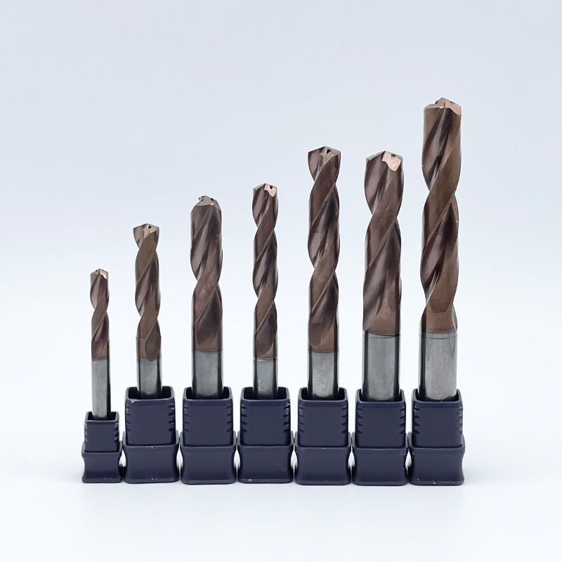
Material & Rigidity | Flexible, prone to deflection in deep holes. | Ultra-rigid micro-grain carbide, zero deflection. |
Coolant Delivery | External flood only. Fails to reach the cutting zone. | Internal dual coolant holes blast chips upward. |
Point Angle | Standard 118 degrees. Wanders easily. | Self-centering 140 degrees for exact positioning. |
Operation Method | Requires constant peck drilling. | Single continuous pass, slashing cycle times. |
Investing in premium deep-hole technology yields a positive return on investment only if the machine can physically support the operational requirements. Two mechanical factors are absolutely non-negotiable. These are spindle runout and coolant delivery capacity.
First, spindle runout must be strictly controlled. Because a solid carbide drill is exceptionally rigid, it lacks the flexibility to absorb misalignment. If the machine spindle has excessive runout, those lateral forces are magnified at the tip of the long tool. This causes the brittle carbide to chatter and eventually shatter deep inside the hole. Upgrading to high-precision hydraulic chucks or shrink-fit tool holders is often necessary to achieve the required concentricity.
Second, the machine must possess adequate high-pressure coolant capabilities. Through-tool coolant systems rely entirely on fluid dynamics to blast chips against the force of gravity. Standard flood coolant pumps are entirely incapable of overcoming the vapor barrier generated at the cutting zone. For bore depths exceeding ten times the diameter, a minimum continuous pressure of one thousand PSI is generally required. Without this sustained pressure, even the most advanced flute geometry will fail due to chip packing.
Success in deep hole machining ultimately comes down to a delicate balancing act. You must clear chips efficiently while maintaining absolute mechanical rigidity. Failing to manage either of these variables leads directly to trapped heat, deflected tools, and eventually, catastrophic tool breakage.
While advanced setups require a higher upfront financial investment, they pay massive dividends on the shop floor. By upgrading to rigid, coolant-fed systems, machinists can drastically reduce cycle times, eliminate the risk of scrapped high-value parts, and achieve unparalleled precision drilling. Over the lifespan of a production run, this approach guarantees the lowest possible cost-per-hole.
Take the time to evaluate your current machining setup and spindle capabilities today. Reviewing your tooling strategy and selecting the right geometry from a trusted manufacturer like SS Endmill can transform your most frustrating deep-hole applications into a highly predictable, profitable process. Explore the full range of high-performance solutions to match your specific material and depth requirements.
In standard engineering terms, any bore with a depth greater than three times its diameter is classified as a deep hole. At this specific depth, standard chip evacuation physics begin to break down. Holes reaching ten, twenty, or up to forty times their diameter enter extreme territory. These require highly specialized tooling, precise pilot holes, and advanced high-pressure coolant systems to prevent failure.
Premature tool breakage is almost universally caused by two empirical factors. These are chip packing and excessive spindle runout. When chips cannot escape the bore, they are recut by the tool, generating massive thermal shock and friction that binds the metal. Alternatively, if the machine spindle lacks rigidity, the resulting deflection places uneven stress on the brittle carbide substrate, causing it to snap. Verifying tool concentricity and upgrading internal coolant flow usually resolves these issues.
Yes, from a metallurgical standpoint, carbide is vastly superior for deep applications. Carbide possesses a much higher stiffness compared to high-speed steel, which drastically reduces tool deflection during operation. Furthermore, carbide can withstand significantly higher cutting temperatures without losing its structural hardness. This added rigidity and thermal stability are absolute prerequisites for machining at extreme depths.
Typically, no. High-performance drills equipped with internal coolant channels are specifically engineered to machine deep bores in a single, continuous feed motion. Using a peck cycle interrupts the constant flow of pressurized cutting fluid and subjects the cutting edge to severe thermal shock as it repeatedly enters and exits the hot cutting zone. Pecking should only be used if your machine lacks the coolant pressure needed to evacuate chips continuously.
Standard flood coolant is physically ineffective for deep hole applications. As the tool penetrates deeper into the workpiece, the centrifugal force of the spinning tool and the escaping chips block external fluid from reaching the bottom of the bore. Furthermore, the immense heat generates a vapor barrier that repels low-pressure liquid. High-pressure, through-tool coolant systems are mandatory to deliver lubrication directly to the cutting edge and force chips upward.
Coolant pressure is the driving force that overcomes gravity and friction inside a deep bore. High pressure forces the cutting fluid through the small internal channels of the drill directly to the cutting edge. This high-velocity fluid cools the carbide, lubricates the cut, and most importantly, physically pushes the sheared chips up the flutes and out of the hole. Insufficient pressure allows chips to stall and pack together, leading to instant tool failure.
When machining stainless steel, heat and material adhesion are your biggest enemies. Aluminum Titanium Nitride coatings are widely considered the best choice for this application. This coating maintains its hardness at extremely high temperatures and provides a smooth surface that prevents the gummy stainless steel from welding to the cutting edge. This drastically improves both chip flow and overall tool life.