- All
- Product Name
- Product Keyword
- Product Model
- Product Summary
- Product Description
- Multi Field Search

Views: 0 Author: Site Editor Publish Time: 2026-08-12 Origin: Site
Selecting the wrong router bit carries hidden operational costs that quickly erode project margins. Excessive secondary sanding, material scrap from tear-out, and machine downtime due to premature tool failure stem directly from poor tooling choices. The core problem lies in balancing the conflicting physics of wood machining. Operators must achieve a flawless top and bottom edge finish while simultaneously evacuating chips fast enough to prevent heat buildup and bit burn.
Wood is an anisotropic material. Its structural properties change depending on the grain direction. Cutting across the grain requires a different shearing action than cutting with it. Furthermore, the adhesives used in engineered woods introduce severe abrasion into the cutting environment. Solving these challenges requires a technical evaluation framework. By selecting the right tooling based on flute geometry, material composition, and precise chipload calculations, you can optimize both cycle times and surface finish.
The fundamental conflict in CNC routing revolves around chip direction and how it interacts with the material fibers. Tools designed to push chips away from the cut path naturally pull the wood fibers upward. This upward lifting action frequently causes top-edge tear-out, especially on veneered or laminated materials. Conversely, tools designed to press the wood fibers downward preserve a pristine top edge but trap waste material inside the kerf. This trapped waste creates a secondary problem: severe friction.
Evaluating heat generation is mandatory for tool longevity. When chips remain trapped in the cut path, the cutting edge recuts the same material repeatedly. This friction generates intense heat, leading directly to bit burn and pitch buildup. Pitch, the natural resin found in wood, melts at high temperatures and coats the cutting edge. Once a bit is coated in pitch, its cutting geometry changes. It no longer shears the wood; it bludgeons it. This exponentially increases friction, overloads the spindle, and leads to rapid degradation of the cutting edge.
The primary goal of optimization is establishing a continuous, appropriately sized chip. A proper chip acts as a heat sink. As the tool shears the material, the generated heat transfers into the chip. When the chip evacuates the kerf, it carries that heat away from the tool and the workpiece. Finding the exact tooling geometry and feed rate to maintain this continuous chip evacuation is the foundation of efficient CNC routing. Operators must constantly monitor the waste stream to ensure the machine produces distinct chips rather than fine dust.
To identify poor chip evacuation on the shop floor, watch for these specific indicators:
Flute geometry dictates how a tool interacts with the material. Selecting the correct geometry requires analyzing the specific operation, the material type, the machine's rigidity, and the desired finish. Using the wrong flute direction guarantees poor results, regardless of how sharp the tool is.
Up-cut bits feature a flute twist that pulls chips upward and out of the cut path. This mechanism provides superior chip evacuation, making them highly efficient for deep pocketing, high-volume material removal, and plunging operations. Because the cutting action pulls upward, these bits leave a clean bottom-edge finish. However, the trade-off is a high risk of top-edge splintering. The upward force also lifts the material. You must use robust workholding systems like high-flow vacuum beds or heavy mechanical clamps to prevent the workpiece from shifting or lifting off the spoilboard during heavy cuts.
Down-cut bits reverse the flute twist, pushing chips downward into the cut. This downward shearing action presses the top fibers of the material flat, making them the best choice for shallow profiling, cutting thin veneers, and applications requiring a pristine top edge. The primary trade-off is poor chip evacuation. Because the chips are forced into the bottom of the kerf, heat generation increases significantly during deep cuts. Operators must utilize multiple shallow passes to prevent bit failure when using down-cut geometries. Never use a down-cut bit for deep plunging, as the trapped chips can cause the bit to snap or start a fire.
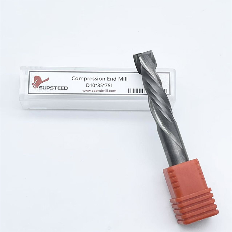
Compression bits engineer a solution to the up-cut versus down-cut dilemma. They combine both geometries on a single cutting edge. The bottom portion of the bit features an up-cut geometry, while the upper portion features a down-cut geometry. This design pushes chips toward the center of the material, leaving both the top and bottom edges flawless. They are the optimal choice for single-pass cutting of double-sided laminates, melamine, and plywood. Using high-quality cnc wood cutting tools like compression bits requires specific CAM programming. The implementation risk involves the initial plunge. The first pass must plunge deeper than the up-cut portion of the bit. If it does not, the up-cut section will tear the top veneer. Operators must use ramping toolpaths to enter the material safely without causing tear-out on entry.
Straight bits feature cutting edges parallel to the tool axis. They are highly user-friendly for beginners doing simple, shallow routing. However, they lack the plunging capabilities and continuous shearing action of spirals. This results in louder operation, increased vibration, and inferior chip clearing. Chipbreakers feature serrated edges designed to break chips into smaller, manageable pieces. This specialized design reduces overall chipload, spindle load, and heat during heavy roughing operations. Chipbreakers allow for fast, clean, and highly efficient material removal in dense hardwoods and thick composites, making them ideal for the first stage of a two-stage roughing and finishing process.
Flute Geometry Selection Matrix
| Geometry Type | Top Edge Finish | Bottom Edge Finish | Chip Evacuation | Ideal Application |
|---|---|---|---|---|
| Up-Cut Spiral | Poor (Prone to tear-out) | Excellent | Excellent (Pulls chips out) | Deep pocketing, blind holes, thick solid wood |
| Down-Cut Spiral | Excellent | Poor (Pushes fibers down) | Poor (Traps chips in kerf) | Shallow profiling, dadoes, thin veneers |
| Compression | Excellent | Excellent | Moderate (Pushes to center) | Single-pass cutting of melamine and plywood |
| Straight Flute | Fair | Fair | Poor | Basic edge routing, low-budget operations |
Beyond standard profile cutting, specialized operations require dedicated tool profiles to achieve specific surface finishes and geometric shapes. Using a standard end mill for a 3D carving or a chamfer will result in massive secondary processing times.
Flat end mills are essential for creating flat-bottomed pockets, precise tenons, and sharp internal corners. While standard router bits often leave a slight radius or uneven bottom due to their center-cutting geometry, flat end mills provide a perfectly perpendicular cut. They are heavily utilized in joinery applications where exact mating surfaces are required for structural integrity. When programming flat end mills for pocketing, ensure your stepover does not exceed 50% of the tool diameter to maintain a clean bottom finish without leaving ridges.
Ball nose bits feature a fully radiused cutting end. They are strictly necessary for 3D carving, topographical modeling, and smooth contouring. The surface finish achieved by a ball nose bit depends entirely on the stepover percentage—the distance the tool moves over for each subsequent pass. A smaller stepover yields a smoother finish with minimal scallop heights, reducing the need for manual sanding. Using precision wood milling cutters for 3D work ensures consistent detail resolution across complex topographies. For high-resolution carvings, a stepover of 8% to 10% of the tool diameter is standard practice.
V-groove bits are the primary tool for chamfering, v-carving, and lettering. The included angle of the bit determines the visual impact of the cut. A 60-degree bit cuts deeper and narrower, providing sharp detail resolution for small text and intricate designs. A 90-degree bit cuts wider and shallower, making it ideal for larger lettering, broad chamfers, and folding applications in composite materials. They are highly versatile and serve as a beginner-friendly option for executing clean, detailed designs without complex 3D toolpaths.
Accurate CNC routing relies on a perfectly flat work surface. Spoilboard surfacing cutters are large-diameter tools, often utilizing insert tooling, designed to skim the top layer of the MDF spoilboard. Maintaining a perfectly tram and level cutting bed is foundational for accurate depth control. If the spoilboard is uneven, a V-carve toolpath will cut deeper in some areas and shallower in others, ruining the design. Regular surfacing ensures the machine's Z-axis remains perfectly calibrated to the material bed.
Follow these steps when setting up a spoilboard surfacing routine:
The composition of the cutting tool dictates its heat resistance, edge retention, and suitability for specific materials. Selecting the right material directly impacts operational efficiency and machine uptime.
High-Speed Steel offers a sharper initial cutting edge than carbide and comes with a significantly lower upfront cost. However, HSS suffers from rapid dulling when exposed to abrasive materials or high heat. In modern production CNC environments, HSS is generally obsolete. The downtime required to constantly change dull HSS bits negates any initial cost savings. It is only viable for low-volume hobbyists cutting very soft woods or foams.
Solid carbide is the standard for professional routing. It provides high rigidity and excellent heat resistance, retaining edge sharpness significantly longer than HSS. The manufacturing process of micro-grain carbide allows for a sharp edge that withstands the rigors of continuous cutting in hardwoods and standard plywoods. The main drawback is its brittleness. Solid carbide is highly susceptible to snapping if feed rates are too aggressive, plunge rates are too fast, or if the spindle exhibits high runout. Operators must ensure their collets are clean and in good condition to minimize runout and protect solid carbide tools.
Insert tooling utilizes a steel tool body equipped with replaceable solid carbide knives secured by screws. The primary evaluation dimension here is cost over time. While the initial tool body requires a higher investment, the long-term operating costs are drastically lower for high-volume shops. When an edge dulls, the operator simply rotates or replaces the insert right on the machine. Furthermore, insert tooling maintains a constant cutting diameter since the tools are never sent out for resharpening. This eliminates the need to update tool libraries in the CAM software constantly. Always use a torque wrench when replacing inserts to ensure they seat properly without warping the tool body.
PCD tools consist of synthetic diamond particles sintered onto a carbide substrate. The evaluation dimension for PCD is extreme longevity in highly abrasive composites like MDF, particleboard, and high-pressure laminates. PCD tools can outlast solid carbide by a factor of 50 or more in these materials. However, they are not recommended for solid natural woods. The manufacturing process of PCD results in a less acute cutting angle compared to carbide, which can cause crushing or tear-out in natural wood grains. PCD tools also require specialized handling, as dropping them on a hard surface will instantly shatter the diamond edge.
Tool Material Characteristics
| Material | Wear Resistance | Shock Resistance | Edge Sharpness | Primary Use Case |
|---|---|---|---|---|
| High-Speed Steel (HSS) | Low | High | Very High | Soft pine, foam, hobby routing |
| Solid Carbide | High | Moderate | High | Hardwoods, plywood, general production |
| Insert Tooling | High | Moderate | High | High-volume surfacing, edge banding prep |
| PCD Diamond | Extreme | Low | Moderate | MDF, particleboard, abrasive laminates |
Tool geometry and material are irrelevant if the machine parameters are incorrect. Optimization relies on calculating and applying the correct chipload. Guessing feeds and speeds leads to broken tools, ruined material, and damaged spindles.
Chipload is the actual physical thickness of the chip removed by one cutting edge during a single revolution. It is the most critical metric in CNC routing. The formula is: Chipload = Feed Rate / (Spindle RPM × Number of Flutes). By manipulating this formula, operators can determine the exact feed rate required for a specific spindle speed to achieve the target chip thickness. For example, if you want a 0.015-inch chipload using a 2-flute bit at 18,000 RPM, you calculate: Feed Rate = 0.015 × 18,000 × 2. The required feed rate is 540 inches per minute.
Feed rate and spindle speed must remain in balance. Increasing the RPM without increasing the feed rate means the tool takes a microscopic bite of material. This creates fine dust rather than distinct chips, leading to massive heat and friction. Conversely, increasing the feed rate without sufficient RPM forces the tool to take a bite larger than its structural capacity. This causes severe tool deflection, poor edge finish, and inevitable tool breakage. You must adjust both variables in tandem to maintain the target chipload.
The number of flutes directly impacts the required feed rate. A single flute tool provides maximum chip clearance. It is ideal for high-speed routing in softer materials like plastics or softwoods, as it allows for aggressive feed rates without packing the kerf with chips. Two and three-flute tools provide a better surface finish because they take more cuts per revolution. However, to maintain the proper chipload with a three-flute tool, the operator must significantly increase the feed rate compared to a single-flute tool. If your machine cannot physically reach the required feed rate for a three-flute bit, you must drop down to a two-flute or single-flute bit to prevent burning.
Optimal parameters are verified through observation. Operators must listen to the machine. A smooth, consistent cutting sound indicates proper parameters. High-pitched screaming or heavy chatter indicates an imbalance between feed and speed. Inspecting the waste material is equally important. The goal is to produce distinct, uniform chips. If the machine is producing fine, powdery dust, the chipload is too low, and the tool is burning up. Adjust feeds and speeds immediately to mitigate premature wear.
Chipload Troubleshooting Guide
| Observed Problem | Likely Cause | Immediate Action Required |
|---|---|---|
| Burn marks on wood edge | Chipload too low (friction) | Increase feed rate or decrease RPM |
| Tool breaks during cut | Chipload too high (deflection) | Decrease feed rate or increase RPM |
| Heavy chatter and vibration | Lack of rigidity or excessive chipload | Check collet, reduce depth of cut, adjust feed |
| Chips packing into the kerf | Poor evacuation or wrong flute geometry | Switch to up-cut bit or add compressed air blast |
Applying a universal tooling strategy across different wood types guarantees failure. Each material requires specific adjustments to mitigate inherent risks. Wood density, grain direction, and adhesive content all dictate how the tool will perform.
Softwoods present a high propensity for fuzzing, crushing, and tear-out due to their loose, soft grain structure. When a dull tool hits soft pine, it crushes the fibers rather than shearing them. To mitigate this risk, utilize razor-sharp down-cut bits or V-bits to press the fibers flat during the cut. Strictly adjust the cutting depth to take shallower passes, reducing the cutting pressure. Maintain high spindle speeds and moderate feed rates to ensure a clean, high-velocity shearing action that slices through the soft grain. Conventional milling is often preferred over climb milling in softwoods to reduce the chance of the tool grabbing and tearing the long fibers.
Dense hardwoods pose the exact opposite problem: excessive heat generation and bit burn. The density of oak or maple creates immense friction against the cutting edge. Mitigation requires strict adherence to chipload charts to ensure the tool is taking a thick enough chip to carry away heat. Use solid carbide spirals designed for heavy chip evacuation. Most importantly, avoid pausing or dwelling the tool in the cut. Any hesitation in tool movement will instantly cause burn marks on the hardwood edge. Ensure your CAM software is programmed with smooth lead-ins and lead-outs to keep the tool moving constantly.
Engineered materials are highly abrasive. The glues and phenolic resins used in MDF destroy cutting edges rapidly. Plywood features alternating cross-grain veneers that splinter easily under upward cutting pressure. To mitigate these risks, compression bits are mandatory for plywood to shear both the top and bottom veneers inward. For MDF and particleboard, utilize PCD diamond tooling or specialized, highly wear-resistant carbide grades designed specifically to withstand abrasive resins. When cutting warped plywood, ensure your vacuum hold-down system is fully optimized, as any material movement will snap a compression bit instantly.
Material Setup Checklist:
Achieving clean edges and efficient chip removal requires abandoning a universal approach. Success in CNC routing depends entirely on geometry-specific and material-specific tooling strategies. Understanding the physics of chip evacuation and heat management allows operators to select the exact tool required for the job, drastically reducing secondary processing and material waste.
A: Compression bits are the optimal choice for plywood. They feature both up-cut and down-cut flutes that push the wood fibers toward the center of the material, preventing splintering on both the top and bottom veneers. You must use a ramping entry toolpath to ensure the down-cut portion engages the top veneer before horizontal cutting begins.
A: Burning occurs due to excessive friction caused by an incorrect chipload. If your feed rate is too low or your spindle RPM is too high, the bit rubs against the wood instead of shearing distinct chips. This rubbing generates intense heat, leading to burn marks and rapid dulling of the cutting edge.
A: Use the formula: Chipload = Feed Rate / (Spindle RPM × Number of Flutes). For example, if your feed rate is 300 inches per minute, your RPM is 18,000, and you use a 2-flute bit, the chipload is 300 / (18,000 × 2) = 0.0083 inches. Compare this result to the tool manufacturer's recommended chipload chart.
A: Up-cut bits pull chips upward, providing excellent chip evacuation for deep cuts but risking top-edge splintering. Down-cut bits push chips downward, leaving a pristine top edge but trapping chips in the kerf, which can increase heat generation in deep cuts. Choose based on which surface requires the cleanest finish.
A: It is highly discouraged. Metal end mills feature flute geometries and rake angles optimized for shearing hard metals, not fibrous wood. Using them on wood typically results in poor chip clearing, severe friction, burning, and a rough surface finish. Always use tools specifically engineered for wood machining.
A: A general rule is to limit the cutting depth to the diameter of the tool (a 1:1 ratio) for standard routing. However, this must be adjusted based on material density, machine rigidity, and tool geometry. You can cut deeper in soft pine than in dense oak, provided chip evacuation remains efficient.