- All
- Product Name
- Product Keyword
- Product Model
- Product Summary
- Product Description
- Multi Field Search

Views: 0 Author: Site Editor Publish Time: 2026-08-22 Origin: Site
Incorrect tooling in CNC woodworking carries a massive financial penalty. Operators frequently ruin expensive hardwood blanks, deal with severe veneer tear-out, or snap bits mid-cut simply because they selected the wrong cutter geometry. The core technical challenge in wood routing involves balancing aggressive material removal with pristine surface finish requirements across variable density wood grain. Wood transfers heat poorly. The tool and the chip must manage all the thermal energy generated during the cut. If chip evacuation fails, friction takes over, leading to burned edges and destroyed tools.
You need a systematic evaluation framework for selecting end mills for woodworking. Tool selection must focus strictly on tool anatomy, flute count mathematics, cutting direction physics, and material-specific tooling strategies. By understanding how flute valleys interact with feed rates and how shear angles dictate edge quality, you eliminate tear-out and maximize tool longevity.
Understanding the physical mechanics of cutting wood is the first step in proper tool selection. Wood behaves entirely differently than metal under a cutting edge. It features a fibrous, directional grain structure that requires specific shearing actions to cut cleanly without splintering. You cannot apply metalworking feeds, speeds, or tool geometries to timber and expect acceptable results.
Chip load represents the physical thickness of the material removed by a single cutting edge during one full revolution of the tool. In woodworking, chip load is the primary mechanism for heat dissipation. Wood acts as an insulator. It does not absorb heat from the cutting process. Therefore, the heat generated by friction must transfer into the wood chip and evacuate the cutting channel immediately. Wood requires a significantly larger chip load than aluminum or steel.
If your chip load is too small, the cutting edge rubs against the wood fibers instead of slicing them. This rubbing generates extreme friction, rapidly burning the wood and destroying the temper of the cutting tool. You calculate chip load using a standard formula: Feed Rate divided by the product of Spindle RPM and the number of flutes. To increase your chip load, you must either increase your feed rate, decrease your spindle speed, or use a tool with fewer flutes.
Every cutting tool represents a physical compromise between chip clearance capacity and structural rigidity. The flute valley is the empty void space between the cutting edges. This space is necessary to channel wood chips up and out of the cut. However, creating a larger flute valley requires removing material from the solid center mass of the tool, known as the core diameter.
An inverse relationship exists here. A tool with massive flute valleys clears chips brilliantly but suffers from a weak, thin core. A tool with a thick, robust core resists bending forces but features shallow flute valleys that easily pack with chips. Woodworking generally prioritizes larger flute valleys because wood chips are bulky and expand upon removal. If the flute valley packs with chips, the tool will snap instantly.
Core Diameter and Chip Clearance Comparison
| Flute Count | Core Diameter Percentage | Chip Clearance Capacity | Structural Rigidity |
|---|---|---|---|
| 1 Flute | Low (~30-40%) | Maximum | Low (Prone to deflection under heavy loads) |
| 2 Flutes | Medium (~50-60%) | High | Moderate (Standard for most routing) |
| 3+ Flutes | High (~70%+) | Low (High risk of packing in wood) | High (Excellent for rigid finishing passes) |
CNC woodworking operations heavily rely on center-cutting geometries. A center-cutting tool features cutting edges that extend all the way to the exact center of the tool face. This specific geometry allows the machine to plunge straight down into the material, exactly like a drill bit. Non-center-cutting tools leave a small void in the middle of the cutting face. They cannot plunge straight down because the non-cutting center would simply crash into the material, causing a fire or breaking the bit.
Because woodworking involves complex pocketing, nesting, and slotting operations that initiate from above the workpiece, center-cutting functionality is mandatory to avoid pre-drilling entry holes. If you must use a non-center-cutting tool, you are forced to program a ramping toolpath, where the bit enters the material at a shallow angle while moving laterally.
Tool rigidity dictates the dimensional accuracy of your final part. Tool deflection occurs when the lateral forces of cutting push the bit off its true vertical axis. This bending causes chatter, poor edge tolerances, and premature tool breakage. A critical rule governs tool rigidity: selecting a bit with excess cutting length beyond your required axial cutting depth exponentially increases deflection.
Think of the end mill as a lever. The collet is the fulcrum. The longer the stick-out, the less force required to bend the tip. If you only need to cut half-inch plywood, using a tool with two inches of cutting length introduces massive, unnecessary leverage against the tool shank. Always select the absolute shortest flute length capable of completing your required depth of cut. A shorter tool runs quieter, leaves a cleaner finish, and lasts significantly longer.
Flute count directly determines how much empty space exists on the tool for chip evacuation. It also dictates the mathematical relationship between your spindle speed and your machine's linear feed rate. Selecting the wrong flute count forces you to run your machine outside its optimal performance envelope.
Single-flute tools offer the absolute maximum flute valley volume possible. They feature one continuous cutting edge and one massive void for chip evacuation. These tools excel in high-speed routing applications involving softwoods or plastics. In these materials, rapid chip evacuation is the primary operational bottleneck.
Softwoods generate large, stringy chips, while plastics melt instantly if chips pack the cut channel. The exceptionally large flute valley prevents chip packing entirely. However, because there is only one cutting edge striking the material per revolution, single-flute tools require significantly higher spindle speeds to maintain an acceptable surface finish and prevent a rippled edge. You must push the machine faster to maintain the correct chip load.
Two-flute tools represent the baseline standard for the vast majority of CNC woodworking operations. They provide an optimal, highly versatile balance. You gain adequate structural tool strength from a thicker core diameter, which prevents deflection during heavy profiling. Simultaneously, the two flute valleys provide sufficient volume for rapid chip removal in most hardwood and plywood applications.
Two-flute tools are the primary choice for center-cutting plunge operations, standard slotting, and general part cutout routines. They allow for moderate spindle speeds and aggressive feed rates, making them the most efficient choice for standard cabinet making and furniture production.
Tools with three or more flutes face strict limitations in woodworking. Adding more flutes drastically reduces the size of the flute valleys. In wood, this creates a high risk of burning and catastrophic chip packing. The bulky wood chips simply cannot escape the restricted valleys fast enough.
High-flute tools serve specific niche applications. They excel during final finishing passes on dense, exotic hardwoods like ipe or wenge. In these scenarios, you remove a microscopic amount of material, so chip volume is negligible. The higher flute count provides more cuts per inch, yielding a glass-smooth surface finish provided you precisely control your feed rates and have a highly rigid CNC gantry.
Feed Rate and Spindle Speed Adjustment Matrix
| Flute Count | Primary Material Focus | Spindle Speed Requirement | Feed Rate Capacity | Chip Evacuation Rating |
|---|---|---|---|---|
| 1 Flute | Plastics, Softwoods, MDF | High (18,000+ RPM) | Moderate to Fast | Excellent |
| 2 Flutes | Hardwoods, Plywood, Melamine | Moderate (12,000 - 18,000 RPM) | Fast | Very Good |
| 3+ Flutes | Dense Hardwood Finishing | Low to Moderate (10,000 - 14,000 RPM) | Very Fast (Requires rigid machine) | Poor (High risk of packing) |
The direction of the cutting shear dictates which face of your material receives a clean edge and which face suffers tear-out. Evaluating upcut vs downcut end mills is the most critical decision for surface finish quality. You must match the shear direction to your specific workholding setup and the location of your delicate veneers.
Upcut tools feature a spiral geometry that creates an upward shearing action. As the tool rotates, it actively pulls wood chips up and out of the cut channel, much like a standard drill bit. This upward extraction makes them the superior choice for deep slotting, heavy pocketing, and high-volume material removal. The chips evacuate instantly, keeping the tool cool.
This upward pulling action rips the wood fibers on the top surface of the material, causing rough edges and splintering. Upcut tools are ideal when top-edge tear-out is acceptable or will be machined away later. The primary implementation risk is workpiece lifting. The upward force can physically pull the material off the machine bed. You must utilize robust workholding, such as a strong vacuum hold-down system or heavy mechanical clamping, to counteract the lifting forces generated by an aggressive upcut bit.
Downcut tools reverse the spiral geometry, creating a downward shearing action. The cutting edges push the wood fibers down into the body of the material as they slice. This downward pressure prevents splintering, leaving a pristine, razor-sharp top edge. Downcut tools are the primary choice for shallow pocketing, cutting dados, and profiling parts where the top surface finish is critical.
The downward action forces all the wood chips to the bottom of the cut trench. This creates a severe implementation risk. The tool constantly re-cuts packed chips at the bottom of the trench, leading to massive heat buildup, extreme friction, and potential fire hazards if pushed too deep. Downcut tools should never be used for deep, single-pass slotting. They also push the material firmly against the spoilboard, which aids in workholding but requires careful monitoring of heat generation.
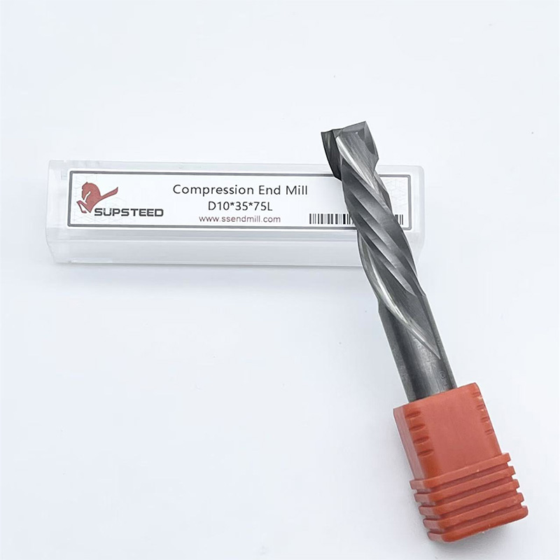
Compression bits combine both geometries into a single tool. They feature an upcut section at the very tip of the bit and a downcut section along the rest of the shank. This forces the chips toward the center of the material. The upcut tip pulls the bottom fibers up, preventing bottom tear-out. The downcut shank pushes the top fibers down, preventing top tear-out.
Compression tools are the mandatory choice for cutting melamine, veneered plywood, and double-sided laminates in a single pass. The critical implementation requirement is depth. Your first cutting pass must be deep enough to fully engage the downcut portion of the bit. If you cut too shallowly, only the upcut tip engages the material, and the tool functions solely as an upcut bit, causing severe top-edge tear-out. For shallow dados on veneered material, operators use specialized "mortise compression" bits, which feature a much shorter upcut section at the tip.
Different wood products require entirely different tooling strategies. You must adapt your cutter selection to the density, grain structure, and chemical composition of the workpiece. A bit that cuts perfectly in MDF will struggle heavily in solid white oak.
Solid hardwoods feature dense, unpredictable grain structures that change direction frequently. These materials require rigid tools that can shear hard fibers without deflecting. For roughing passes where material removal is the priority, utilize a 2-flute upcut tool to clear chips rapidly and prevent heat buildup.
For final profiling passes where edge quality matters most, switch to a 2-flute downcut tool. This two-tool strategy ensures fast cycle times without sacrificing the top surface finish. Pay close attention to grain direction. Climb milling (where the tool feeds in the direction of rotation) often produces a cleaner finish on figured hardwoods by reducing the lifting force on the grain, though it requires a highly rigid CNC machine to prevent chatter.
Softwoods present a unique challenge due to their fibrous, resinous nature. The soft fibers tend to crush and fuzz rather than shear cleanly. Plastics present a melting risk due to heat generation. Both materials require extreme sharpness and massive chip clearance.
Utilize 1-to-2 flute upcut bits featuring razor-sharp edges. O-flute designs excel here. The O-flute geometry provides a curved, highly polished flute valley that curls the chip efficiently and slices soft fibers cleanly without generating excess friction. The polished flute prevents soft resins and melted plastics from adhering to the tool body.
Engineered woods consist of wood particulates or veneers bound together by abrasive chemical glues. These adhesives destroy cutting edges rapidly. Furthermore, the brittle veneers on plywood and melamine chip instantly if cut improperly. You must manage both the abrasive glues and the fragile surfaces.
Deploy compression bits for all through-cuts on engineered panels to protect both the top and bottom faces. To combat rapid edge wear from the adhesives, utilize tools with specialized hard coatings like DLC (Diamond-Like Carbon) or AlTiN (Aluminum Titanium Nitride). These coatings drastically extend tool life in abrasive environments, maintaining the edge geometry long after an uncoated bit would have dulled.
Protecting your tooling investment requires understanding the environmental factors that degrade cutting edges during operation. Tool failure is rarely a defect in the carbide; it is almost always an operational error regarding heat management or maintenance.
Wood naturally contains resins and pitch. When a tool generates friction, these resins melt and adhere directly to the hot cutting edges. This pitch accumulation alters the cutting geometry, fills the flute valley, and drastically increases friction, creating a destructive cycle.
You must mitigate this through proper chip load calculation. Ensure the chip is thick enough to carry the heat away from the tool. Establish a routine chemical cleaning schedule. Soak your collets and bits in dedicated resin-dissolving solvents to remove pitch buildup before it bakes onto the carbide permanently. A dirty collet loses its gripping force, leading to tool slippage and severe runout.
Tool material directly impacts performance. Solid micro-grain carbide stands as the absolute standard for CNC woodworking. It provides vastly superior edge retention and stiffness compared to high-speed steel (HSS) or carbide-tipped alternatives.
Woodworking requires specific edge geometry. Tools must feature high rake angles to create razor-sharp edges capable of slicing fibrous materials cleanly. This contrasts heavily with metalworking tools, which utilize blunter edge geometries to withstand heavy impact forces. Never use blunt metalworking end mills for finish passes on wood. They will pound the fibers instead of cutting them, leaving a crushed, burned edge.
Tool coatings offer significant advantages in specific materials but hinder performance in others. Coated tools provide excellent return on investment when cutting highly abrasive engineered woods like MDF or fiberglass-reinforced plastics. The coating acts as a thermal and physical barrier against abrasive wear.
Uncoated, highly polished flutes often perform better in raw, solid wood. The polished surface prevents natural wood resin from adhering to the tool, maintaining the sharpest possible cutting edge and ensuring a cleaner shear on natural fibers. Coatings slightly round over the microscopic cutting edge, which is acceptable in abrasive MDF but detrimental when trying to slice soft pine fibers cleanly.
Troubleshooting Common CNC Routing Defects
| Defect Observed | Probable Cause | Tooling Solution |
|---|---|---|
| Burn marks on cut edge | Friction from low chip load | Increase feed rate, decrease RPM, or use fewer flutes. |
| Top edge veneer tear-out | Upward shear lifting fibers | Switch to a downcut or compression end mill. |
| Bottom edge tear-out | Downward shear pushing fibers out | Switch to an upcut or compression end mill. |
| Tool snapping mid-cut | Chip packing or excessive deflection | Reduce flute length, clear chips with air blast, check collet grip. |
| Chatter marks on finish pass | Tool deflection or machine vibration | Use a shorter tool, increase core diameter, check spindle tram. |
A: A 2-flute end mill is the best all-around choice for cutting wood. It provides an optimal balance between structural core strength and sufficient flute valley volume for rapid chip evacuation. Single-flute tools are better for high-speed plastic routing, while 3-flute tools should be restricted to very light finishing passes on dense hardwoods.
A: Use upcut end mills for deep slotting, pocketing, and rapid material removal where chip evacuation is critical, acknowledging it may splinter the top edge. Use downcut end mills for shallow pockets, dados, and profiling where a pristine, tear-free top surface finish is required, but avoid pushing them too deep.
A: While they will physically cut wood, metalworking end mills are not recommended for woodworking. They feature blunter edge geometries designed for impact resistance against steel. Wood requires high rake angles and razor-sharp edges to cleanly slice fibers. Metalworking tools often cause rubbing, friction, and burning in wood.
A: Burning occurs due to extreme friction caused by an inadequate chip load. If your spindle speed is too high or your linear feed rate is too slow, the tool rubs the wood instead of slicing it. This traps heat in the cut channel. Increase your feed rate or decrease your spindle speed.
A: A compression end mill features an upcut geometry at the tip and a downcut geometry on the shank. It pushes chips toward the center of the material. It is absolutely necessary when cutting double-sided materials like melamine or veneered plywood to prevent tear-out on both the top and bottom faces simultaneously.
A: Using a tool with a flute length significantly longer than your required axial cutting depth creates a lever effect. The lateral cutting forces push against this excess length, causing the tool to bend off its vertical axis. This deflection causes chatter, poor dimensional accuracy, and eventual tool snapping.
A: To prevent tear-out on veneered plywood, use a compression end mill and ensure your first cutting pass plunges deep enough to fully engage the downcut portion of the tool. Alternatively, use a downcut bit for a shallow scoring pass on the top veneer before switching to an upcut bit to clear the remaining material.