- All
- Product Name
- Product Keyword
- Product Model
- Product Summary
- Product Description
- Multi Field Search

Views: 0 Author: Site Editor Publish Time: 2026-08-04 Origin: Site

Using the wrong tooling in non-metal machining carries a steep operational cost. Scrapped parts from melted plastics, torn wood grain, and delaminated composites quickly erode profit margins. Many operators assume standard metal-working tools transition seamlessly to softer or fibrous materials. This assumption leads to expensive failures. Wood, plastics, and composites demand highly specific chip evacuation strategies and precise heat management that standard metal tooling cannot provide. Standard end mills lack the necessary flute clearance, causing excessive friction, chip packing, and catastrophic part failure.
To achieve clean cuts and maximize tool longevity, operators must adopt a technical evaluation framework. Selecting the correct routing end mills requires analyzing material properties, flute geometry, cut direction, production volume, and specific industry applications like cabinetry, sign making, and aerospace prototyping.
Defining a successful cut depends entirely on the material on your spoilboard. Success criteria generally include a flawless edge finish, strict dimensional accuracy, and extended tool longevity. Achieving these goals requires understanding how different materials react to cutting forces. Non-metals behave vastly differently than steel or aluminum under a spinning spindle. You cannot force a one-size-fits-all approach.
Wood introduces unique biological and engineered variables into the machining process. Solid wood has distinct grain directions. Cutting against the grain often causes splintering and unpredictable tear-out. Knot density varies wildly across a single board, creating sudden spikes in cutting resistance that can snap fragile bits. You have to account for these natural inconsistencies when programming your toolpaths.
Engineered woods like MDF and plywood present entirely different challenges. They contain highly abrasive urea-formaldehyde adhesives and resins. These glues dull cutting edges much faster than natural wood fibers. Tear-out is the primary failure mode when routing veneered wood. Top-edge tear-out occurs when the cutter lifts the surface veneer. Bottom-edge tear-out happens when the tool pushes through the bottom layer without support. Preventing this requires matching the shear angle of the cutter to the specific layer you need to protect.
Machining plastics like acrylics, polycarbonate, and HDPE requires strict temperature control. The primary failure mode here is heat generation. Excessive heat leads to chip welding. This occurs when melted plastic fuses back onto the cutter or the workpiece. It leaves a rough, recast edge that ruins the part and often breaks the tool as the flutes pack solid with hardened plastic.
Rapid chip evacuation is far more important than sheer cutting force. You must remove the hot chip from the cutting zone instantly. Extruded acrylic melts much faster than cast acrylic, requiring even more aggressive chip clearance. Interestingly, tools optimized for plastics often serve dual purposes. Many sign makers use single-flute CNC routing cutters to cleanly cut light aluminum. The massive chip clearance prevents material galling in soft metals just as it prevents melting in plastics.
Composite materials combine strong fibers with rigid resins. This combination is notoriously difficult to machine. The fibers are highly abrasive. They act like sandpaper against the cutting edge. Standard tools lose their sharpness almost immediately when cutting carbon fiber, fiberglass, or Garolite (G-10). The glass and carbon dust also wreaks havoc on machine components if not properly extracted.
Delamination is the main risk during entry and exit cuts. If the tool pulls upward, it can separate the composite layers. Fraying occurs when dull tools fail to shear the tough fibers cleanly, leaving a fuzzy edge that requires manual post-processing. Machining composites requires specialized geometries that compress the layers together while cutting, ensuring the fibers shear rather than bend.
The physical shape of the cutter determines how chips move. It also dictates how forces apply to the workpiece. Selecting the right geometry is non-negotiable for clean finishes. You have to match the tool's physical action to the material's weakness.
Up-cut geometries feature flutes that spiral upward. They act like an auger. This design excels at lifting chips out of deep grooves and blind pockets. It prevents chip packing and heat buildup. However, the upward lifting force causes top-edge fraying on laminated materials. It also requires highly rigid workholding. Weak vacuum hold-downs will fail as the tool lifts the part right off the table.
Down-cut geometries push chips downward into the cut. This downward pressure preserves the top surface finish perfectly. It leaves a crisp, clean edge on veneers and prevents thin parts from lifting. The drawback is poor chip evacuation. Pushing chips into a blind pocket causes severe heat buildup and can start fires in wood dust. Down-cut tools are best suited for through-cuts where chips can escape underneath the material into a spoilboard.
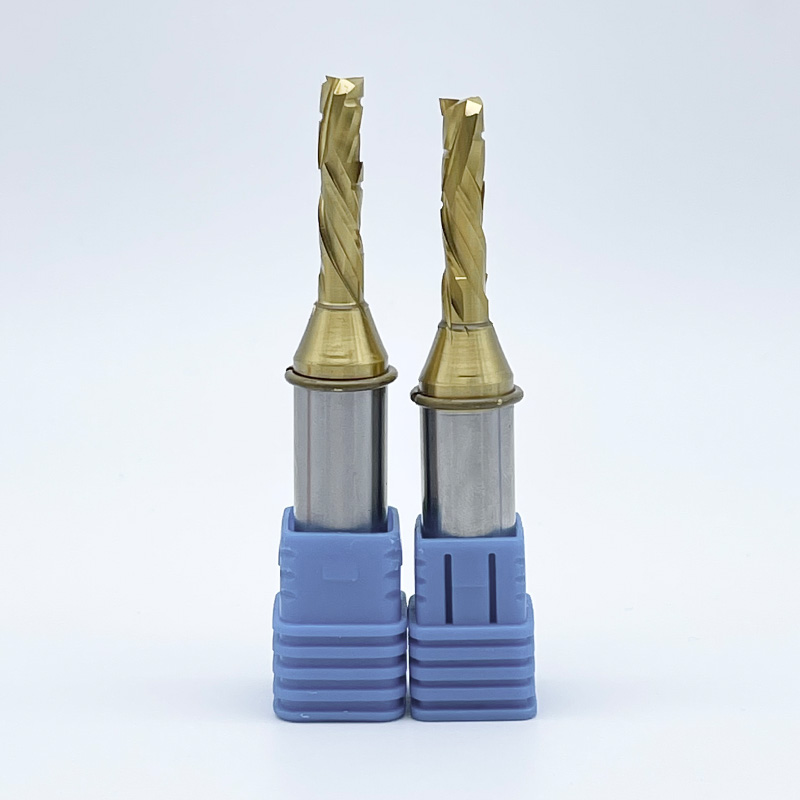
Compression tools solve the dilemma of double-sided laminates. They feature a dual-action geometry. The tip of the tool has an up-cut spiral. The shank portion has a down-cut spiral. These opposing forces meet near the center of the material.
This design pulls the bottom edge up and pushes the top edge down simultaneously. It is the ultimate solution for cutting melamine and double-sided plywood. You achieve clean top and bottom edges in a single pass. The tool must pass completely through the material for the compression effect to work properly. If you are cutting shallow dados, you need a "mortise compression" bit, which features a much shorter up-cut section at the tip.
Flute count shares an inverse relationship with chip clearance. More flutes mean less space for chips to escape. Fewer flutes provide massive gullets for rapid evacuation.
The tip profile determines the shape of the cut bottom and the entry dynamics. Flat tips handle general profiling and pocketing tasks. Fishtail geometries feature a slight inward angle at the tip. This allows them to produce clean, flat-bottomed plunge cuts in sheet goods without splintering the surface.
Ball-nose profiles are essential for 3D surfacing. They create smooth contours and complex organic shapes in foam, wood, and modeling board. V-groove profiles serve specific niche applications. They excel at chamfering edges and routing precise lettering for sign making. They are also used extensively for miter-folding composite panels to create seamless corners without secondary joining operations.
Geometry Selection Guide
| Material Category | Primary Challenge | Recommended Geometry | Optimal Flute Count |
|---|---|---|---|
| Solid Hardwood | Grain tear-out, splintering | Up-cut or Down-cut | 2 to 3 Flutes |
| Laminated Plywood | Top and bottom veneer chipping | Compression | 2 Flutes |
| Acrylic / Plastics | Heat generation, melting | Up-cut (O-flute) | 1 Flute |
| Carbon Fiber | Abrasion, delamination | Down-cut or Diamond pattern | Multiple / PCD |
The substrate of the cutting tool determines its lifespan. Machining abrasive non-metals requires hard, durable materials. Soft tool steel will fail rapidly on a CNC router.
High-Speed Steel (HSS) is generally unsuitable for high-production CNC routing. HSS dulls incredibly fast when exposed to abrasive wood glues or composite fibers. The rapid dulling leads to burning, poor finishes, and excessive spindle load. We dismiss HSS for serious production environments entirely.
Solid carbide stands as the industry standard. It offers exceptional hardness and rigidity. Micro-grain solid carbide maintains a sharp edge far longer than HSS. It withstands the abrasive nature of MDF and plastics. While the initial acquisition is higher, the cost-to-performance ratio makes solid carbide the baseline requirement for any professional shop.
Highly abrasive applications demand extreme solutions. Carbon fiber, fiberglass, and high-pressure laminates destroy standard carbide quickly. Polycrystalline Diamond (PCD) tooling is the answer. PCD inserts are brazed onto a steel or carbide tool body.
PCD offers unmatched hardness. It resists abrasion better than any other material on earth. The initial acquisition cost of PCD is high. However, the extended tool life drastically improves the return on investment. In continuous production of abrasive composites, PCD reduces the overall cost-per-part by eliminating frequent tool changes and machine downtime.
Coatings enhance tool performance by reducing friction and increasing surface hardness. Zirconium Nitride (ZrN) is highly effective for machining plastics and soft aluminum. It creates a slick surface that prevents plastic chips from adhering to the flute. Diamond-Like Carbon (DLC) coatings provide extreme hardness and lubricity. DLC extends tool life in abrasive woods and composites while keeping cutting temperatures low.
Selecting the right tool is only half the battle. Implementing it correctly requires balancing physical constraints and machine capabilities. Poor implementation ruins good tooling.
Achieving deep cut depths presents a significant challenge. Long tools act like levers. The longer the tool, the more it deflects under cutting pressure. Tool deflection causes chatter, poor dimensional accuracy, and snapped bits.
Follow a strict rule of thumb on the shop floor. Always choose a tool with the shortest Length of Cut (LOC) possible for your required depth. Pair this with the thickest shank diameter your collet can hold. Maximizing shank thickness and minimizing LOC ensures maximum rigidity and stable cutting dynamics. If you are cutting 0.75-inch plywood, an LOC of 0.875 inches is perfect. Using a 2-inch LOC for that same cut invites vibration.
Chip load is the physical size of the chip removed by each cutting edge. It is the most critical metric in routing. You calculate it by dividing your feed rate by your spindle RPM multiplied by the number of flutes. You must balance feed rates with spindle RPM to achieve the target chip load.
Running RPMs too high while keeping feed rates too low causes catastrophic failure. The tool rubs against the material instead of cutting it. This rubbing generates massive friction. It burns wood, melts plastic, and rapidly dulls the cutting edge. You must feed the tool fast enough to let the chip carry the heat away from the cut zone.
Tool geometry dictates how you enter the material. Straight plunging places immense stress on the bottom of the cutter. It often causes burning on the bottom surface, packs chips into the flutes, and reduces tool life.
Ramping into a cut is generally preferred. Ramping involves moving the tool laterally while simultaneously plunging downward at a shallow angle (usually 2 to 5 degrees). This strategy distributes the cutting force along the side flutes. It extends tool life, prevents bottom-surface burning, and clears chips more effectively during entry.
Your tooling choices must align with your machine's physical capabilities. Using aggressive up-cut bits on machines with weak vacuum hold-down systems is a major implementation risk. The lifting force of the up-cut geometry will overpower the vacuum. This leads to part movement, ruined workpieces, and potential safety hazards. Always match the cut direction to your clamping strength. If your vacuum is struggling, switch to a down-cut bit to help hold the material flat against the spoilboard.
Troubleshooting Common Machining Defects
| Defect Observed | Probable Cause | Corrective Action |
|---|---|---|
| Melted plastic edges | RPM too high, feed too slow | Decrease RPM, increase feed rate, use O-flute |
| Top edge tear-out on wood | Up-cut geometry lifting fibers | Switch to down-cut or compression bit |
| Burn marks on wood | Friction from rubbing, dull tool | Increase feed rate, replace worn tooling |
| Tool breakage at collet | Excessive deflection, LOC too long | Reduce LOC, increase shank diameter, check collet wear |
Choosing the right tool does not have to be guesswork. Follow this systematic framework to evaluate your specific application and select the optimal geometry for your next job.
A: While possible for light work or hobbyists, metal-cutting tools typically have too many flutes. This leads to poor chip evacuation, burning in wood, and melting in plastics. If forced to use them, feed rates and RPMs must be drastically adjusted to prevent immediate failure.
A: Single-flute (O-flute) solid carbide bits are the absolute best choice. Their unique geometry provides massive gullets. This allows them to eject chips rapidly and prevents the friction-induced heat buildup that causes acrylic to melt and weld to the tool.
A: Plywood has delicate veneers on both sides. A compression bit features opposing shear angles. The up-cut tip pulls the bottom veneer up, while the down-cut shank pushes the top veneer down. This prevents tear-out on both surfaces simultaneously.
A: The specific geometry of a fishtail cutter features a slight inward angle at the tip. This design allows for clean, flat-bottomed plunge cuts directly into sheet goods. It shears the material cleanly without tearing the surface veneer during entry.
A: We highly recommend 2-flute or 3-flute designs for MDF. These configurations perfectly balance the need for a smooth edge finish with adequate chip clearance. MDF produces dense, abrasive dust, so maintaining proper clearance is vital to prevent burning.
A: Chip welding is caused by excessive heat generation. It occurs when spindle RPMs are too high, feed rates are too slow, and flute clearance is inadequate. The plastic melts from friction and fuses back onto the tool or the cut edge.
A: Prevent delamination by using down-cut or compression geometries. These designs push the abrasive fibers downward during the cut. Always ensure your tool is razor-sharp. Dull edges pull and tear fibers instead of shearing them cleanly. Additionally, ramp into your cuts rather than plunging straight down.