- All
- Product Name
- Product Keyword
- Product Model
- Product Summary
- Product Description
- Multi Field Search

Views: 0 Author: Site Editor Publish Time: 2026-08-20 Origin: Site

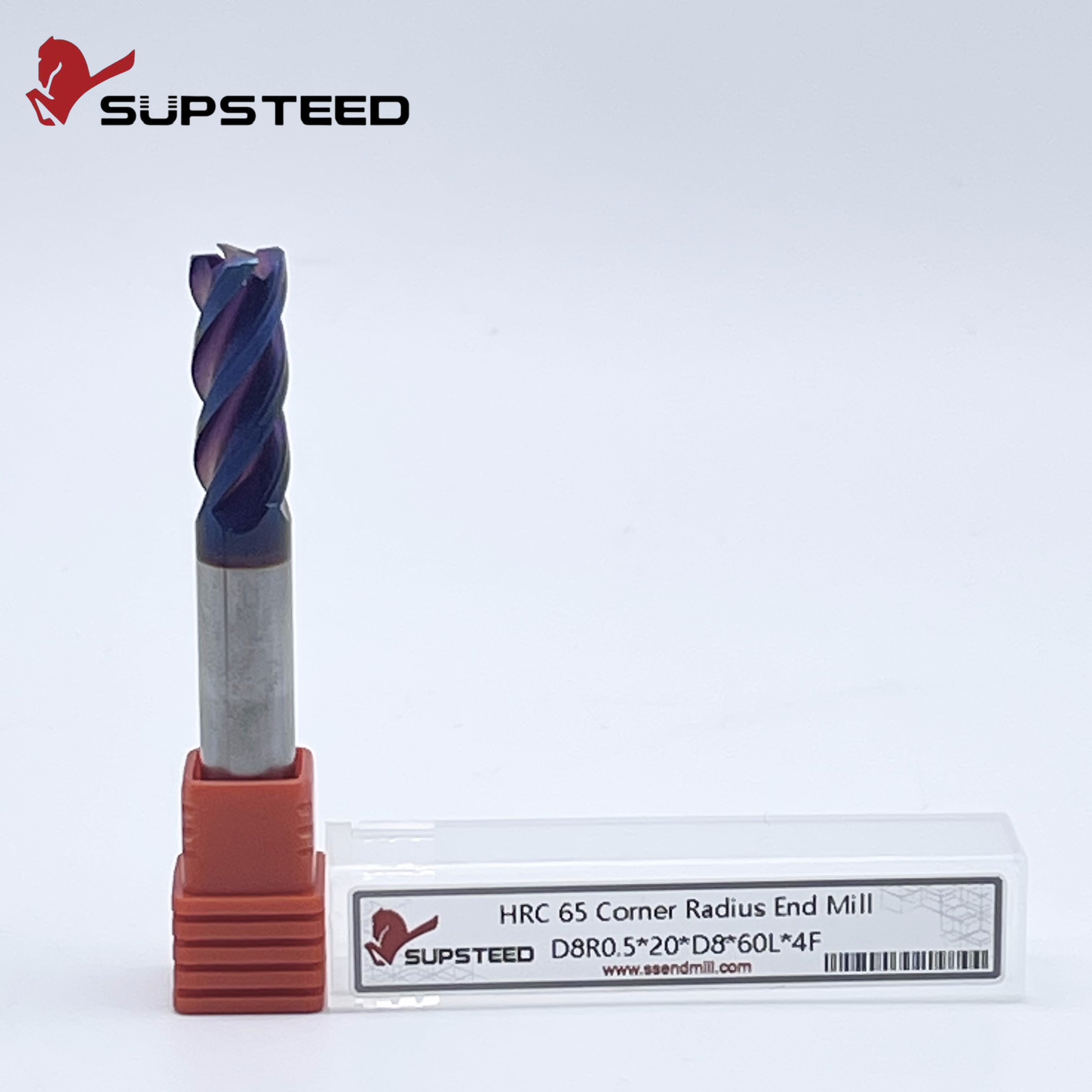
Sharp corners on square end mills act as severe stress concentrators during heavy milling. When you push these tools under high cutting forces, the 90-degree intersections experience micro-chipping. This edge degradation rapidly accelerates into catastrophic tool failure. Unpredictable tool life and frequent tool changes drive up consumable costs, increase machine downtime, and jeopardize part tolerance, especially in hard or abrasive materials. You must distinguish between a corner radius end mill and a corner rounding tool. A corner rounding end mill is a form tool used exclusively to machine a radius onto the external edge of a finished part. A corner radius tool is a flat-bottomed cutter featuring radiused corners designed for edge strength during pocketing and profiling. Transitioning to this geometry fundamentally alters how cutting forces distribute across the tool edge. Understanding this mechanical impact helps machinists maximize metal removal rates without sacrificing process reliability.
Force Distribution: A corner radius dissipates cutting forces over a larger surface area, significantly reducing the localized stress that causes sharp corners to chip.
Material-Specific Gains: Tough, abrasive, and brittle materials demand edge reinforcement; utilizing a specialized titanium corner radius end mill or hardened steel corner end mill can extend tool life by up to 50% compared to square profiles.
The Deflection Trade-Off: While a larger radius increases edge strength, it also redirects cutting forces radially, requiring more rigid setups to prevent chatter and tool deflection.
Part Geometry Constraints: The maximum allowable corner radius is dictated by the part print's internal corner requirements; engineers must balance tool strength against the need for secondary rest-machining operations.
Metal cutting forces concentrate at the sharpest point of contact. On a standard square end mill, the 90-degree transition between the flute and the end face takes the entire cutting load. This sharp corner acts as a massive stress riser. When the tool hits the workpiece, the mechanical pressure and shock of the interrupted cut focus entirely on this fragile tip. Adding a radius smooths the transition between the peripheral and end cutting edges. This geometric change distributes the mechanical load over a curved surface area rather than a single microscopic point. By spreading the cutting forces, the localized pressure on the carbide matrix drops. This prevents the edge from fracturing under heavy chip loads. When roughing a deep pocket in 4140 steel, a square tool will often snap its corners within minutes. The radiused tool survives because the force spreads out evenly across the curve, preventing the localized stress from exceeding the transverse rupture strength of the carbide.
Wear patterns differ drastically between square and radiused tools. A square end mill typically fails starting right at the corner. Initial micro-chipping occurs almost immediately during high-load roughing. Once the corner chips, the tool loses its protective geometry. This exposes the softer inner substrate and accelerates flank wear along the entire flute length. A radiused tool resists this initial micro-chipping. The curved edge deflects the shock of entering the cut. Because the edge remains intact longer, the tool maintains its designed cutting geometry. You get a predictable, gradual wear pattern rather than sudden, catastrophic edge degradation. Machinists can plan tool changes based on time in cut rather than reacting to a broken tool alarm. Furthermore, the radius helps mitigate notch wear at the depth of cut line, a common issue when machining work-hardening materials.
Heat generation is a constant challenge in milling operations. Sharp corners lack the physical mass required to absorb and dissipate heat effectively. The tip of a square end mill quickly reaches critical temperatures. This leads to thermal cracking and premature failure. The added material at the corner of a radiused tool provides significantly greater thermal mass. This extra carbide acts as a heat sink. It pulls thermal energy away from the cutting edge and distributes it into the body of the tool. This enhanced heat dissipation is highly beneficial during dry machining or high-speed applications where thermal shock is a primary failure mode. When running air blast instead of coolant, that extra mass keeps the cutting edge from burning up, allowing you to maintain aggressive surface footage without melting the tool.
End Mill Geometry Comparison
Geometry Type | Edge Strength | Bottom Finish | Primary Application |
|---|---|---|---|
Square | Low | Excellent (True Flat) | General purpose, sharp internal corners |
Chamfered | High | Good | Heavy roughing in cast materials |
Ball Nose | Very High | Poor (Scalloped) | 3D surfacing, complex contours |
Corner Radius | High | Excellent (Flat Center) | High-efficiency roughing, profiling |
Square end mills have strict operational limits. Avoid them in applications involving interrupted cuts, high-hardness materials, or heavy roughing. Edge fragility becomes a massive liability here. When machining forgings with heavy scale or running dynamic toolpaths with variable radial engagement, the sharp corners of a square tool chip prematurely. If the part print does not explicitly demand a sharp 90-degree internal corner, defaulting to a square end mill unnecessarily limits your feed rates. It compromises process stability. You end up babying the tool just to keep the corners intact, which destroys your shop's overall productivity and metal removal rates.
Both corner radii and corner chamfers protect the cutting edge. They distribute forces differently. A radius provides a smooth, continuous curve that dissipates cutting forces evenly. This makes it ideal for profiling, pocketing, and stable finishing operations. A chamfer creates a faceted edge protection. It replaces one 90-degree corner with two obtuse angles. Chamfers offer excellent strength and work well for heavy roughing in specific cast materials. However, they do not provide the smooth force transition of a radius. A radius generally leaves a superior surface finish on adjacent walls and floors, whereas a chamfer can sometimes leave visible witness marks if the step-over is not perfectly calculated.
Ball nose end mills possess exceptional structural strength. The entire cutting end is a continuous radius. However, they are highly inefficient for machining flat-bottomed pockets. A ball nose tool leaves a scalloped finish on flat floors. You need incredibly tight step-overs to achieve an acceptable surface. Furthermore, the surface speed of a ball nose tool drops to zero at the very center of the tip. This varying surface speed causes the tool to push and rub material at the center rather than shearing it cleanly. This leads to uneven wear and poor tool life in flat-bottom applications, forcing you to run secondary finishing passes with a flat tool anyway.
The corner radius geometry serves as the optimal hybrid. It provides the flat-bottom cutting efficiency of a square mill combined with the structural integrity of a ball nose. The flat center of the tool ensures uniform surface speed across the majority of the cut. This allows for efficient material removal on pocket floors. Meanwhile, the radiused corners protect the most vulnerable part of the tool from chipping. This balance makes the geometry highly versatile. It handles aggressive roughing parameters while still delivering excellent floor finishes, allowing you to consolidate your tool carousel and reduce cycle times.
Titanium alloys present unique machining challenges. They have low thermal conductivity and a strong tendency to work-harden. Heat generated during the cut does not dissipate into the chip. Instead, it concentrates right at the cutting edge. Utilizing a titanium corner radius end mill is essential for managing this thermal load. The specific radius size prevents the rapid edge breakdown associated with titanium machining. It ensures stable semi-finishing by maintaining a consistent tool profile. The smooth transition of the radius helps resist built-up edge. This is a common issue in aerospace applications where workpiece material welds to the tool face, altering the cutting geometry and causing sudden tool breakage.
Machining tool steels and hardened alloys ranging from 45 to 65 HRc requires exceptional tool rigidity. The cutting pressures generated in these high-hardness applications will immediately fracture the sharp corners of a standard square tool. Selecting a hardened steel corner end mill is mandatory. The reinforced corner withstands the immense compressive forces without fracturing the carbide matrix. This allows machinists to maintain productive feed rates in hardened materials without fear of sudden tool failure. You ensure dimensional accuracy across long production runs, eliminating the need to constantly offset the tool to compensate for rapid corner wear.
Brittle materials like cast iron, ceramics, and advanced composites are highly susceptible to edge breakout and fracture. When a sharp tool enters these materials, the localized pressure often causes the workpiece material to chip away rather than shear cleanly. Applying corner radius tools in these applications mitigates this risk. The radius eases the tool into the cut, reducing the initial engagement shock. This gradual entry prevents immediate fracture upon entry. It protects both the cutting edge and the structural integrity of the brittle workpiece, drastically reducing your scrap rate on expensive castings.
High-Efficiency Milling toolpaths rely on maintaining a consistent chip load and controlling the tool's engagement angle. Corner radius tools pair perfectly with HEM strategies. During dynamic roughing, the tool experiences varying radial engagements and fluctuating chip loads as it navigates complex pocket geometries. The reinforced radius absorbs these dynamic forces far better than a square edge. It prevents the micro-chipping that often occurs when a tool rapidly enters and exits the cut during trochoidal milling. The tool survives the entire roughing cycle. Additionally, the radius alters the radial chip thinning calculation. Because the chip thickness varies along the curve of the radius, machinists must compensate by increasing the feed rate to maintain the target chip thickness, preventing the tool from rubbing and work-hardening the material.
When machining 3D profiles and semi-finishing complex contours, tool geometry directly impacts surface quality. Utilizing a profiling corner radius cutter offers distinct advantages over square tools. The radius minimizes the cusp height left on contoured surfaces. Because the tool edge is curved, it blends step-downs more smoothly than the sharp corner of a square mill. This reduction in cusp height significantly decreases secondary polishing time. It improves the overall surface finish of the final part, making it highly effective for mold making and aerospace structural components. The mathematical relationship between the radius size and the step-down dictates the theoretical surface finish, allowing programmers to optimize their toolpaths for maximum efficiency without sacrificing part quality.
Recommended Corner Radii by Material Hardness
Material Hardness (HRc) | Tool Diameter | Recommended Radius Range | Primary Benefit |
|---|---|---|---|
Under 30 HRc (Aluminum, Mild Steel) | 0.500" | 0.015" - 0.030" | Basic edge protection, minimal radial push |
30 - 45 HRc (Pre-hardened Steels) | 0.500" | 0.030" - 0.060" | Balances strength with cutting efficiency |
45 - 65 HRc (Tool Steels, Hardened Alloys) | 0.500" | 0.060" - 0.125" | Maximum fracture resistance under extreme load |
Selecting the correct radius size involves balancing edge strength against cutting force direction. A small radius, typically ranging from .015" to .030", provides adequate edge protection with minimal impact on the direction of cutting forces. This size is ideal for less rigid setups, long-reach applications, or machining thin-walled parts where minimizing radial pressure is critical. A large radius, ranging from .060" to .125", maximizes tool strength and extends tool life significantly. However, a larger radius pushes cutting forces radially into the part and the spindle. This increased radial pressure raises the risk of chatter. It requires a highly rigid machine and workholding setup to operate effectively. If your spindle bearings are worn or your fixture lacks mass, a large radius will induce severe vibration.
The part print often dictates the maximum allowable tool radius. Engineers frequently face the dilemma of machining inside corner radii specified by the designer. A fundamental rule of Design for Manufacturing is to avoid using a tool with a radius exactly matching the part's internal corner radius. If you use a .250" radius tool to cut a .250" inside corner, the tool will wrap around the corner. This drastically increases its engagement angle. This causes engagement shock, severe chatter, and potential tool breakage. Choose a tool radius slightly smaller than the internal corner. Using a .187" radius tool for a .250" corner allows the CAM software to interpolate the corner smoothly. This maintains a consistent chip load and prevents tool wrap, ensuring a clean finish in the corners.
The structural benefits of a radiused geometry are fully realized only when paired with an exceptionally rigid substrate. Solid micro-grain carbide is the industry standard for these tools. A carbide corner radius end mill provides the stiffness required to resist deflection under heavy loads. The synergy between the rigid carbide substrate and the reinforced corner geometry creates a tool capable of sustaining high metal removal rates in demanding materials. High-speed steel or cobalt tools simply lack the rigidity to maximize the benefits of the radiused edge. They flex and induce chatter before the edge strength limit is reached, negating the advantages of the geometry entirely.
Advanced PVD and CVD coatings, such as AlTiN or TiSiN, perform significantly better on a radiused edge than on a sharp corner. Coatings applied to a sharp 90-degree point are prone to flaking off under mechanical stress. The smooth curve of a radius allows the coating to adhere more uniformly and securely. Because the coating remains intact longer, the tool retains its thermal barrier and lubricity. This further extends tool life and maintains edge sharpness throughout the machining process. When cutting abrasive materials like cast iron or high-silicon aluminum, this coating retention is the primary factor in achieving acceptable tool life.
The primary risk when implementing larger corner radii is the increase in radial cutting forces. These forces push the tool away from the workpiece, inducing deflection and chatter. To mitigate this, machinists must maximize setup rigidity. Utilizing shrink-fit or hydraulic tool holders provides superior gripping force and concentricity compared to standard collet chucks. Reducing tool overhang to the absolute minimum required for clearance is also critical. If chatter persists, adjusting the radial depth of cut or increasing the feed per tooth can help stabilize the cut. This forces the tool to bite into the material rather than rubbing against it.
Setup Rigidity Checklist for Radiused Tools:
Verify spindle runout is below 0.0002" to ensure even chip loads across all flutes.
Seat the workpiece directly on precision parallels or dedicated fixture plates to eliminate vibration.
Use hydraulic or shrink-fit tool holders to maximize gripping torque and concentricity.
Keep tool stick-out to the absolute minimum required to clear the deepest pocket.
Transitioning to radiused tools requires specific adjustments within your CAM software. Programmers must ensure the software accurately accounts for the exact corner radius of the physical tool. Failing to define the radius correctly will result in gouging the part or leaving unexpected stock on flat floors and inside corners.
Follow these programming steps to ensure accuracy:
Measure the physical tool radius using an optical comparator or presetter before building the tool library entry.
Input the exact radius value into the CAM tool definition to generate accurate offset paths.
Enable rest-machining functions to automatically detect un-machined material left in sharp internal corners.
Program subsequent operations with smaller tools to clear remaining stock using reduced feed rates to prevent chip load spikes.
Audit your current square end mill usage to identify high-wear applications in roughing operations or hard metal machining.
Run a controlled A/B test comparing your standard square tool against a radiused alternative to quantify the return on investment in extended tool life.
Update your CAM tool libraries to reflect the exact corner radii of your new cutters to prevent gouging and ensure accurate rest-machining toolpaths.
Upgrade your tool holding to shrink-fit or hydraulic chucks to counteract the increased radial forces generated by larger corner radii.
A: A corner radius end mill is a flat-bottom cutting tool with radiused corners used to mill pockets, slots, and profiles while maintaining edge strength. A corner rounding tool is a specialized form cutter used solely to machine a curved radius onto the outside edge of a previously machined part.
A: Depending on the material and application, adding a corner radius can extend tool life by 20% to 50%. The radius prevents the initial micro-chipping that causes sharp corners to fail, allowing the tool to wear predictably and remain in the cut significantly longer.
A: Yes. Unlike a ball nose end mill, a corner radius tool has a flat center cutting geometry. It efficiently machines flat pocket floors while the radiused corners protect the outer edges of the tool from chipping during the roughing and finishing passes.
A: For titanium, a radius between .030" and .060" is generally ideal. This size provides enough edge reinforcement to resist the high thermal and mechanical loads of titanium machining without generating excessive radial forces that could cause chatter in the setup.
A: A corner radius redirects a portion of the cutting forces radially, pushing against the tool and spindle. While this increases edge strength, it requires a more rigid setup to prevent deflection. Spindle load may increase slightly due to the larger engagement area at the corner.
A: Using a tool with a matching radius causes the cutter to fully engage the corner all at once. This sudden increase in tool engagement causes shock, chatter, and potential tool breakage. Always use a tool with a slightly smaller radius to allow smooth CAM interpolation.