- All
- Product Name
- Product Keyword
- Product Model
- Product Summary
- Product Description
- Multi Field Search

Views: 0 Author: Site Editor Publish Time: 2026-08-16 Origin: Site
Machining stainless steel presents specific mechanical challenges on the shop floor. The material has low thermal conductivity and a high tendency for work hardening. These physical properties make tool geometry a primary failure point during milling operations. Selecting an incorrect flute count directly results in poor chip evacuation, tool breakage, premature edge wear, and scrapped parts. These failures drive up tooling costs and extend cycle times.
While traditional rules of thumb exist, modern tool path strategies like High-Efficiency Milling (HEM) have shifted how we approach material removal. You must match the tool's physical structure to the specific cutting dynamics of the programmed path. This guide provides a technical framework for selecting the exact flute count based on operation type, machine rigidity, tool reach, and material removal rate (MRR) goals.
Stainless steel alloys, particularly 300-series austenitic grades like 304 and 316, possess poor thermal conductivity. When you machine aluminum or low-carbon steel, the chip absorbs the vast majority of the heat generated by the shearing action. The chip carries that heat away from the cutting zone. Stainless steel behaves differently. It absorbs significantly less heat, forcing the thermal load directly into the cutting tool and the workpiece itself.
Flute count dictates the thermal cycle of the end mill. The number of cutting edges determines the exact ratio of time the edge spends engaged in the material generating heat versus rotating through the air or coolant. A higher flute count means each individual cutting edge spends less time cooling before re-entering the cut. If the tool lacks adequate cooling time, thermal shock and rapid edge degradation occur. You must balance the need for high feed rates with the tool's ability to dissipate thermal loads.
Work hardening is the most destructive variable when milling stainless alloys. If the cutting edge rubs against the material rather than shearing it cleanly, the surface layer immediately hardens. Subsequent passes then impact a surface significantly harder than the base material, destroying the cutting edge instantly. When the cutting edge radius is larger than the actual chip thickness, the tool compresses the material. This compression alters the grain structure, spiking the surface hardness.
Flute count directly impacts the required feed rate to prevent this rubbing action. To maintain a proper chip load, the machine must feed the tool at a specific rate. Tools with higher flute counts require significantly higher table feed rates to maintain the same chip load per tooth. If the machine cannot achieve or maintain these feed rates, the chip thickness drops below the cutting edge radius.
To prevent work hardening on the shop floor, follow these steps:
Tool design is always a compromise between core rigidity and chip evacuation capacity. The core diameter determines the tool's resistance to deflection under heavy lateral loads. The flute valleys, or gullets, determine how much physical space exists to evacuate the sheared material. Increasing the core diameter shrinks the gullets, while deepening the gullets weakens the core. A standard 4-flute tool typically utilizes a core diameter that is roughly 60% to 65% of the tool's outer diameter.
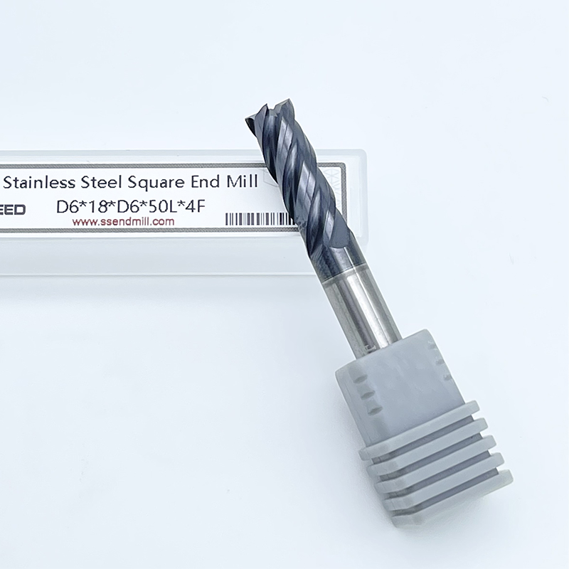
For decades, 4 flute end mills for stainless steel have served as the foundational standard because they strike the optimal mathematical balance. A 4-flute geometry retains enough core web thickness to resist the high shear forces required to cut stainless. At the same time, it provides large enough gullets to evacuate the stringy, tough chips characteristic of the material. This balance prevents the tool from snapping under load while simultaneously preventing chips from packing into the flutes.
The 4-flute configuration excels in traditional, heavy-cut programming where the tool engages a large percentage of its diameter. Standard slotting operations, where the radial depth of cut equals the tool diameter (1xD), demand massive chip clearance. In these confined cuts, chips have nowhere to go but up the flutes. A 4-flute tool provides the necessary evacuation space to prevent recutting chips, which would otherwise lead to immediate tool failure.
Heavy roughing and general profiling also benefit from this geometry. When utilizing older CNC equipment that lacks the processing speed for dynamic tool paths, you rely on heavier, slower cuts. The robust core and spacious gullets of a 4-flute tool handle these traditional parameters reliably. However, these tools face strict limitations when attempting high-speed finishing passes or modern dynamic milling strategies, where fewer flutes limit the maximum achievable feed rate.
Standard flutes often struggle with the long, continuous chips produced by certain stainless grades. To combat this, manufacturers developed serrated or corncob roughing end mills. These specialized tools feature notches ground into the cutting edges, designed specifically to break the chip into small, manageable pieces rather than allowing it to form a continuous string.
These roughers are typically manufactured in 4-flute or 5-flute configurations. By breaking the chip at the source, the tool drastically reduces the volume of material occupying the gullet at any given moment. This mechanical advantage eliminates the chip packing risks normally associated with heavy material removal rates in stainless steel. Roughing end mills allow you to push the tool harder and deeper, maximizing roughing efficiency before coming in with a standard end mill for the final finishing pass.
Modern CAM software has popularized High-Efficiency Milling (HEM), a strategy that fundamentally changes how tools engage the workpiece. HEM utilizes a very low radial depth of cut (RDOC) paired with a very high axial depth of cut (ADOC). Instead of taking shallow, wide cuts, HEM takes deep, narrow cuts. This approach distributes tool wear evenly across the entire length of the flute rather than localizing it at the tip.
When the RDOC drops below 50% of the tool's diameter, a phenomenon called radial chip thinning occurs. The actual thickness of the chip becomes significantly less than the programmed feed per tooth. For example, at a 10% radial engagement, the actual chip thickness is roughly 60% of the programmed feed. To compensate and maintain a proper chip load, you must increase the table feed rate dramatically. This is where 5-flute and 6-flute tools dominate. Because the narrow cut produces a very thin, small chip, massive gullet space is no longer necessary. The higher flute count allows the machine to run at exponentially higher feed rates without overloading any individual cutting edge.
Surface finish quality is directly tied to the distance the tool advances per revolution and the number of cutting edges engaging the material. When finishing, the goal is to minimize the scallop height left behind by the tool's rotation. Higher flute counts achieve superior finishes because they place more cutting edges on the workpiece per revolution, allowing for a smoother surface profile.
Tools with 6, 7, or even 9 flutes are strictly reserved for these finishing passes. During a finishing operation, the material removal rate is minimal, meaning chip evacuation is a negligible concern. The primary requirement is extreme tool rigidity to prevent deflection, which causes dimensional inaccuracies and surface chatter. The massive core diameter of high-flute tools provides this necessary rigidity, ensuring the tool stays perfectly true to the programmed path.
Deploying high-flute tools requires strict discipline regarding tool path engagement. The primary failure mode for 5-flute and 6-flute end mills is chip packing. Because the core diameter is so large, the gullets are extremely shallow. If you attempt to drive a 6-flute tool into a heavy slotting cut or a tight internal pocket, the chips will instantly jam inside the flutes.
Once chips pack into the gullets, the tool stops cutting and begins extruding the material. This causes immediate galling, where the stainless steel friction-welds itself to the carbide cutting edge. Within seconds of this occurring, the torque load exceeds the tool's structural limits, snapping the end mill off in the spindle. High-flute tools must be restricted to low-radial engagement paths where chips can easily escape the cutting zone.
Operational Parameters by Flute Configuration
| Flute Count | Primary Application | Radial Engagement (RDOC) | Core Rigidity Level | Chip Evacuation Capacity |
|---|---|---|---|---|
| 3 Flutes | Deep, narrow slotting | 100% (Slotting) | Low | Maximum |
| 4 Flutes | General purpose, heavy roughing | 25% - 100% | Medium | High |
| 5 Flutes | Dynamic roughing (HEM) | 10% - 25% | High | Moderate |
| 6+ Flutes | Finishing, very light profiling | < 10% | Maximum | Low |
A common misconception among novice programmers is that tools with massive chip clearance will solve chip packing issues in tough materials. In aluminum machining, 2-flute and 3-flute tools are the absolute standard because aluminum is soft, cuts easily, and produces massive volumes of chips that require deep gullets for evacuation. Applying this logic to stainless steel is a costly error.
The failure mechanics of a 2-flute tool in stainless steel are straightforward. Stainless requires immense shear force to cut. A 2-flute tool possesses a very thin core web, often less than 50% of the outer diameter, to accommodate its large gullets. When this weak core encounters the high cutting forces required for stainless, the tool deflects severely. Tool deflection follows the formula of length cubed over diameter to the fourth power. This means core diameter is the single biggest factor in tool stiffness. The deflection causes aggressive harmonic chatter, immediate edge chipping, and rapid tool failure. 2-flute tools simply lack the structural integrity required to survive the mechanical demands of stainless alloys.
While 2-flute tools are entirely unsuited for stainless, 3-flute tools occupy a very specific, rare niche. In extreme edge cases involving very deep, narrow slotting, standard 4-flute tools may still pack with chips despite their balanced geometry. When the slot depth exceeds standard parameters, getting coolant down to the cutting zone and evacuating chips out of the deep channel becomes nearly impossible.
In these highly specific scenarios, a 3-flute tool serves as a hybrid compromise. It provides significantly better chip evacuation volume than a 4-flute tool while maintaining just enough core rigidity to survive the cut. Utilizing a 3-flute tool in stainless requires extremely rigid workholding, a robust machine spindle, and heavy, high-pressure coolant to flush the deep slot continuously. It is not a general-purpose solution, but rather a targeted fix for problematic slotting.
The selection process begins by analyzing the CAM strategy. Traditional heavy-cut programming dictates a lower flute count. If the tool path involves plunging, full-width slotting, or heavy step-overs exceeding 30% of the tool diameter, a 4-flute end mill is mandatory to handle the chip volume.
Conversely, modern trochoidal or dynamic milling paths demand higher flute counts. If the CAM software is generating peeling tool paths with a 5% to 15% radial engagement, utilizing a 4-flute tool leaves massive productivity on the table. In these dynamic paths, 5-flute and 6-flute tools should be the default choice, allowing the programmer to push table feed rates to the machine's maximum reliable limit.
Flute count cannot be evaluated in a vacuum. It must be paired with the correct Length of Cut (LOC). The fundamental rule of milling tough alloys is to minimize the LOC to only what is strictly necessary to complete the feature. Tool deflection increases exponentially with length. A tool that is twice as long will deflect eight times as much under the same load.
Combining a high flute count with an unnecessarily long flute length exacerbates harmonic chatter. While the high flute count provides a thicker core, the excessive length negates that rigidity. When machining deep pockets in stainless, you should utilize relieved-shank tools. These tools feature a short cutting length at the tip, followed by a reduced-diameter neck that provides reach without the weakness of extended flutes.
The physical capabilities of the CNC machine dictate tool selection just as much as the workpiece material. High-flute tools require high feed rates to maintain minimum chip loads. If a 6-flute tool requires a feed rate of 250 inches per minute to prevent work hardening, the machine must be capable of accurately interpolating complex geometry at that speed.
Older commodity machines often lack the servo acceleration and deceleration capabilities to maintain high feed rates through tight corners. When the machine slows down to navigate a corner, the chip load drops, the tool rubs, and the stainless work hardens. If the machine lacks dynamic rigidity or processing speed, you must revert to lower flute counts to keep feed rates within the equipment's operational envelope.
Flute density directly correlates with the required coolant delivery method. When selecting end mills for stainless steel, you must evaluate your coolant systems. High flute counts create small, dense gullets. Clearing chips from these confined spaces requires significant mechanical force.
Standard flood coolant is often insufficient for 5-flute and 6-flute tools engaged in deep pockets. The coolant pools in the cavity, failing to flush the chips away from the cutting zone. High-pressure through-spindle coolant (TSC), often running at 1000 PSI, or aggressive programmable air blasts are mandatory. These systems blast chips out of the small gullets before the tool rotates back into the cut. If high-pressure evacuation is unavailable, you must reduce the flute count to provide larger physical escape routes for the chips.
Selecting the correct flute count is only the first step in optimizing tool geometry. Symmetrical tools, where the flutes are spaced exactly equally around the circumference, generate rhythmic impacts as each cutting edge strikes the material. In tough alloys like stainless, this rhythm quickly builds into a resonant frequency, causing harmonic chatter that destroys surface finishes and shatters carbide edges.
To mitigate this, premium end mills utilize variable pitch and variable helix geometries. Variable pitch alters the spacing between the cutting edges. For example, a 4-flute tool might have indexing at 88 degrees, 92 degrees, 89 degrees, and 91 degrees. Variable helix alters the angle of the flute as it spirals up the tool. These intentional irregularities break up the timing of the impacts, preventing resonant frequencies from forming. When machining stainless steel, variable geometry is an absolute requirement regardless of the chosen flute count.
The high thermal loads generated by multi-flute engagement require advanced surface coatings to protect the carbide substrate. Uncoated carbide degrades rapidly when exposed to the heat and abrasion of stainless steel. Tool coatings act as a thermal barrier and provide lubricity to prevent built-up edge.
Aluminum Titanium Nitride (AlTiN) and Titanium Aluminum Nitride (TiAlN) are the standard coatings for stainless applications. These coatings thrive in high-heat environments. As the tool heats up during the cut, the aluminum in the coating oxidizes at roughly 800 degrees Celsius. This forms a microscopic layer of aluminum oxide, shielding the carbide from thermal shock. Pairing the right flute count with an AlTiN coating ensures the tool can survive the aggressive parameters of modern HEM strategies.
When tools fail prematurely, the failure mode provides direct evidence of geometric mismatch. You must inspect worn or broken tools to adjust your strategies accurately.
A: No. 2-flute end mills have a very weak core web designed for massive chip evacuation in soft materials like aluminum. When applied to stainless steel, the high shear forces cause immediate deflection, severe chatter, and rapid tool breakage.
A: 6-flute tools have very large cores and shallow gullets. If you drive them into confined pockets or heavy radial cuts, the chips cannot escape and immediately pack into the flutes. This causes the tool to gall and snap. Restrict 6-flute tools to light finishing passes or low-engagement dynamic milling.
A: Radial chip thinning occurs when the radial depth of cut is less than 50% of the tool diameter. The actual chip thickness becomes smaller than the programmed feed per tooth. You must increase the feed rate to maintain the proper chip load and prevent the tool from rubbing and work-hardening the stainless steel.
A: While not strictly necessary for all operations, roughing end mills with serrated edges are highly recommended for heavy material removal. They break the stringy stainless chips into small pieces, preventing chip packing and allowing for much more aggressive roughing parameters.
A: Variable pitch alters the spacing between the cutting edges. Instead of striking the material in a perfect rhythm, the uneven spacing breaks up the timing of the impacts. This prevents resonant frequencies from forming, effectively eliminating harmonic chatter and extending tool life.
A: AlTiN (Aluminum Titanium Nitride) or TiAlN coatings are optimal. These coatings are designed for high-heat applications. As the tool heats up, the coating forms an aluminum oxide layer that protects the carbide substrate from thermal shock and wear.