- All
- Product Name
- Product Keyword
- Product Model
- Product Summary
- Product Description
- Multi Field Search

Views: 0 Author: Site Editor Publish Time: 2026-08-19 Origin: Site
Machining deep cavities, high-wall profiles, or complex 5-axis features forces a direct choice between tool clearance and system rigidity. Utilizing standard tooling for deep-reach applications often results in shank rubbing, catastrophic tool failure, or excessive deflection. This deflection leads directly to chatter and rejected parts on the inspection table. Selecting the wrong extended-reach tool geometry unnecessarily sacrifices stiffness, reducing material removal rates and increasing cycle times. You cannot afford to guess when programming deep pockets. Selecting the optimal tool geometry requires moving beyond basic catalog dimensions. This guide evaluates the structural differences, performance trade-offs, and application criteria between reduced shank and long reach geometries to ensure predictable machining outcomes. We will break down exactly how to manage tool deflection while maintaining the necessary clearance for efficient deep-cavity milling.
Misunderstanding tool nomenclature leads directly to incorrect tool selection. On the shop floor, operators sometimes use terms like "long reach," "long flute," and "reduced shank" interchangeably. This creates severe process instability. Selecting a tool with a flute length longer than necessary drastically reduces the core diameter. This reduction in core material strips away structural integrity. You get excessive tool deflection, poor surface finishes, and unpredictable tool life. Accurate identification of tool geometry balances the need for physical reach with the demand for maximum rigidity. We see shops scrap expensive aerospace parts simply because a programmer selected a long flute tool when a relieved neck was required.
The term reduced shank end mills carries a dual meaning in the machining industry. First, it refers to tools where the gripping shank is physically smaller than the cutting diameter. For example, a tool might feature a 1/2-inch cutting diameter but utilize a 3/8-inch shank to accommodate specific collet sizes or spindle limitations on smaller CNC machines. Second, it refers to tools designed with a "necked" or relieved portion immediately behind the cutting edge. This specific geometry provides clearance, preventing the non-cutting portion of the tool from rubbing against the walls of a deep pocket or slot.
The physical geometry consists of a short active cutting edge, followed immediately by a diameter reduction. This clearance zone extends up to the gripping shank. The transition from the cutting diameter to the reduced neck must be carefully engineered with a specific radius. A sharp corner here creates a stress concentration that leads to the tool snapping under load. When radial forces push against the cutting edge, that transition radius absorbs the brunt of the stress.
Historically, machinists performed shop-floor modifications. They custom-ground standard shanks down on a pedestal grinder to create clearance for deep pockets. While this solves the immediate clearance issue, it destroys the tool's balance and concentricity. Factory-ground tools offer superior balance, precise transition radii, and controlled runout. This results in significantly longer tool life and predictable machining dynamics. You cannot achieve high-speed machining parameters with a hand-ground tool shank.
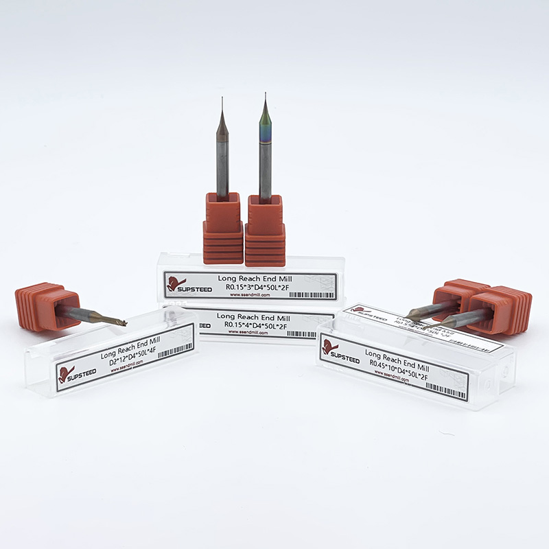
long reach end mills feature a standard gripping shank diameter that is equal to or larger than the cutting diameter. Below the gripping shank, these tools feature an extended, relieved neck, commonly referred to as the Length Below Shank (LBS). At the very end of this extended neck is a short flute length. This fluted section is typically only as long as the required maximum depth of cut for a given pass.
The primary function of this geometry is to reach deep into a workpiece without the upper shank interfering with the part walls. By keeping the fluted section short, the tool maintains a solid, un-fluted cylindrical neck for the majority of its extended length. This solid neck provides a massive structural advantage over tools fluted along their entire length. The un-fluted carbide acts as a rigid extension of the spindle, transferring cutting forces efficiently without bending.
Long flute end mills feature cutting edges that extend continuously along the working length of the tool. While they seem like an obvious choice for deep pockets, they are rarely the optimal solution. The core trade-off lies in the tool's cross-sectional area. A long flute tool requires deep chip gullets cut into the carbide along its entire length. This continuous removal of core material makes the core diameter significantly smaller over a longer distance.
When a tool has a smaller core diameter over a long distance, overall rigidity plummets. In deep pocketing, you rarely engage the entire flute length simultaneously. Therefore, using a long flute tool simply to achieve depth introduces unnecessary weakness. Long reach tools with relieved solid necks are preferred because the un-fluted neck retains maximum core material. This provides the stiffness necessary to resist radial cutting forces and prevent chatter. If you only need a 0.250-inch depth of cut at the bottom of a 3-inch deep pocket, a tool with 3 inches of flute length is a massive liability.
Assessing how tool geometry impacts physical machining forces requires looking beyond static dimensions. When a tool engages material at the bottom of a deep cavity, radial and axial forces act upon the extended length. This creates a lever effect against the spindle bearings. Managing these forces requires a strict evaluation of rigidity, deflection, clearance, and chip evacuation dynamics. You must understand the physics of the cut to program the machine effectively.
Tool deflection is the primary enemy of deep cavity machining. The mathematics of deflection dictate that a tool's tendency to bend increases as a cube of the overhang length and decreases as the fourth power of the diameter. If you double the length of the tool hanging out of the holder, it becomes eight times more flexible. If you halve the core diameter of the tool, it becomes sixteen times more flexible. This is not a linear relationship; it is an exponential curve that destroys part tolerances.
This mathematical reality explains why a long reach tool with a thick, un-fluted neck is exponentially more rigid than a long flute tool of the same overall length. The solid neck maximizes the diameter variable in the deflection equation. Conversely, reduced shank tools, where the neck diameter is aggressively reduced to clear complex geometry, are highly vulnerable to deflection. The exact points of stress concentration occur at the transition radius between the cutting diameter and the reduced neck, and at the transition between the neck and the main gripping shank. Excessive radial engagement will cause the tool to pivot at these stress points. This leads to instant catastrophic failure.
To calculate deflection on the shop floor, programmers use the cantilever beam formula. While you do not need to run the math for every cut, understanding that a 10% reduction in neck diameter results in a nearly 40% loss in rigidity changes how you approach feed rates. You must compensate for this lost rigidity by altering your toolpath strategy.
In complex 5-axis machining, clearance requirements extend beyond the immediate cutting zone. As the machine spindle tilts to approach high-wall profiles, the toolholder and the upper shank of the tool risk colliding with the workpiece. Reduced shank tools provide critical clearance for multi-axis tilting. They allow the cutting edge to engage the material while the relieved neck and smaller shank safely bypass overhanging part features.
When selecting these tools, machinists must calculate the required clearance based on part draft angles and wall heights. The Length Below Shank (LBS) metric defines the maximum safe reach before the full-diameter shank contacts the part. Accurate LBS measurements ensure the tool can reach the bottom of the feature without inducing a catastrophic spindle crash. You must account for the physical envelope of the toolholder nut as well, especially when using ER collet systems in tight trunnion setups.
Evacuating chips from a deep cavity presents a significant fluid dynamics challenge. Short flutes on long reach tools evacuate chips efficiently from the immediate cutting zone. However, once the chips leave the short flutes, they must travel up the un-fluted neck to exit the cavity. This requires external assistance. High-pressure air blast or through-spindle coolant is mandatory to blast chips out of the deep pocket and prevent them from falling back into the cutting path.
Flute count optimization plays a critical role here. Selecting tools with fewer flutes, such as 2 or 3-flute designs, provides larger chip valleys. These larger valleys are critical for evacuating larger chips out of deep pockets without packing. If a 4 or 5-flute tool is used in a deep, confined pocket, the smaller chip gullets will quickly pack with material. This leads directly to tool breakage. The chips have nowhere to go, so they weld to the cutting edge.
Furthermore, there is a severe risk of chip recutting in deep pockets when using relieved neck tools. Unlike long flute tools, which act like continuous augers pulling chips up and out, relieved neck tools leave chips suspended in the cavity. If coolant pressure is insufficient, the tool will recut these hardened chips, destroying the cutting edge instantly. Programmable coolant nozzles or high-pressure through-tool air are non-negotiable for these operations.
Matching the tool geometry to the specific machining operation prevents scrapped parts and broken tooling. The decision framework relies on analyzing the part geometry, the required material removal rates, and the limitations of the machine tool setup. You cannot apply a one-size-fits-all approach to extended reach milling.
Reduced shank tools are highly specialized and should be deployed only when part geometry demands them. They are the ideal use case for machining features wider than the shank. Operations such as undercutting, T-slotting, or clearing overhanging part features require a cutting diameter that is larger than the neck or shank to prevent interference.
They are also necessary when utilizing smaller toolholders in tight machining envelopes. If a machine spindle is limited to a maximum collet size of 3/8-inch, but a 1/2-inch cutting diameter is required for a specific corner radius, a reduced shank tool bridges that gap. Regarding material considerations, these tools are best suited for softer materials like aluminum or plastics, or for light finishing passes in harder materials where radial cutting forces are minimal. Pushing a reduced shank tool hard in Inconel or 4140 steel will result in immediate tool failure.
Long reach tools are the workhorses of deep cavity machining. Their ideal use cases include deep cavity roughing and finishing, mold making, and reaching over clamps or fixtures. Because they retain a solid, full-diameter shank and a thick relieved neck, they can withstand higher cutting forces than their reduced-shank counterparts.
In micro-machining applications, the role of long-neck micro end mills is critical. In medical and electronics manufacturing, reaching deep micro-cavities requires extreme precision. A long-flute micro tool is far too fragile to survive the cutting forces. A relieved neck micro tool provides the necessary rigidity to machine these microscopic features without snapping. We frequently use 0.031-inch diameter tools with a 0.250-inch reach in medical implant manufacturing, relying entirely on the solid neck for stability.
For material considerations, long reach tools are fully capable of handling harder alloys, including titanium and tool steels. However, the depth of cut and feed rates must be strictly optimized for the neck diameter, not the cutting diameter, to manage deflection. You must program the toolpath based on the weakest point of the tool.
Establishing a baseline for acceptable surface finish and dimensional accuracy dictates the tooling strategy. Success in deep cavity milling requires defining the maximum allowable tool overhang-to-diameter ratio. Standard milling operations operate comfortably at a 3:1 ratio. Deep cavity milling pushes this to 5:1 or even 10:1.
Once the ratio exceeds 5:1, standard cutting parameters no longer apply. Specialized vibration-dampening strategies, such as variable pitch flutes, highly balanced toolholders, and modified toolpaths, are required to maintain dimensional accuracy and prevent chatter marks on the finished walls. You must also consider the spindle condition; worn spindle bearings will amplify the vibration of an extended reach tool, making it impossible to hold tight tolerances.
Tool Geometry Comparison Guide
| Geometry Type | Primary Advantage | Primary Limitation | Best Application |
|---|---|---|---|
| Reduced Shank | Allows cutting features wider than the shank; fits smaller collets. | Lowest rigidity; highly prone to deflection under heavy loads. | Undercutting, T-slotting, light finishing in tight envelopes. |
| Long Reach (Relieved Neck) | High rigidity for deep reach; prevents wall rubbing. | Chips must be evacuated past the un-fluted neck via air/coolant. | Deep cavity roughing and finishing, mold making. |
| Long Flute | Continuous cutting edge; acts as an auger for chip evacuation. | Small core diameter over a long distance causes severe chatter. | Deep peripheral profiling where full flute engagement is required. |
Deploying extended-reach tooling introduces significant operational challenges. The physical length of the tool acts as a lever, amplifying any inaccuracies in the spindle, toolholder, or toolpath. Mitigating these risks requires adjustments across speeds, feeds, toolholding, and CAM programming. You cannot treat a 6-inch long tool the same way you treat a 2-inch long tool.
You cannot run an extended-reach tool at the same parameters as a standard-length tool. The loss of stiffness necessitates a reduction in chip load (Inches Per Tooth) and depth of cut (axial and radial). Pushing a long reach tool too hard radially causes the tool to bend away from the cut, resulting in tapered walls and severe chatter.
To compensate, machinists must utilize high-feed milling strategies. High-feed milling involves taking a very light axial depth of cut combined with a very high feed rate. This specific strategy directs the cutting forces axially up the spindle, rather than radially against the weakened neck. By pushing the forces up into the rigid spindle bearings, the tool remains stable, allowing for high material removal rates even at extended lengths.
When adjusting parameters, start by dropping your radial engagement to 5% or 10% of the tool diameter. Maintain a high surface footage to keep the heat in the chip, but reduce the feed per tooth by 20% to 30% compared to a standard length tool. Monitor the spindle load meter closely during the first pass. If you hear high-pitched squealing, the tool is deflecting. Drop the radial depth of cut immediately. Do not drop the feed rate first, as this causes rubbing and work-hardening of the material.
Runout Amplification at Extended Lengths
| Toolholder Type | Runout at Collet Face | Runout at 4-Inch Overhang | Impact on Tool Life |
|---|---|---|---|
| Standard ER Collet | 0.0005 inches | 0.0020 inches | Severe reduction; uneven chip load causes rapid edge failure. |
| Precision Milling Chuck | 0.0002 inches | 0.0008 inches | Moderate reduction; acceptable for roughing passes. |
| Shrink Fit / Hydraulic | 0.0001 inches | 0.0004 inches | Maximum tool life; even chip load prevents chatter. |
The toolholder is the foundation of extended-reach machining. Standard ER collets are insufficient for long reach applications due to stack-up runout. An ER collet system relies on multiple mating tapers, each introducing a microscopic amount of runout. When a tool hangs out 5 inches from the spindle, a runout of 0.0005 inches at the collet face translates to massive runout at the cutting edge.
To mitigate this, mandate the use of shrink fit, hydraulic chucks, or precision milling chucks. Shrink fit holders provide 360-degree clamping force directly on the tool shank, eliminating mating tapers and minimizing Total Indicator Runout (TIR). Controlling runout ensures that every flute takes an equal chip load, preventing premature tool wear and catastrophic vibration. If one flute takes a heavier chip than the others due to runout, it will push the tool off-center, initiating a chatter cycle that destroys the surface finish.
Accurate tool definition in CAM software is non-negotiable. Programmers must input the exact neck diameters, Length Below Shank, and flute lengths. If the CAM software assumes the tool has a continuous flute or a different neck diameter, it will generate toolpaths that crash the non-cutting shank into the workpiece.
Toolpath strategies must also adapt to the tool's geometry. Avoid full slotting at all costs, as this maximizes radial engagement and guarantees chatter. Instead, utilize helical entry to enter the material gently. Implement trochoidal or dynamic milling toolpaths. These strategies maintain a constant, light tool engagement angle, managing radial loads and preventing the tool from burying itself in corners.
Follow this procedure when setting up extended reach tools in your CAM system:
A: A long reach tool features a short active cutting edge at the tip and a solid, relieved un-fluted neck extending up to the shank. This solid neck provides high rigidity. A long flute tool has cutting edges machined along its entire extended length, which reduces the core diameter and makes the tool highly susceptible to bending and chatter.
A: This tool geometry is used to prevent the non-cutting shank from rubbing against the walls of a deep pocket. It also allows machinists to use a larger cutting diameter in a smaller toolholder, and it enables the machining of undercuts or T-slots where the cutting feature is wider than the shank.
A: While a relieved neck is slightly less rigid than a full-diameter shank due to the reduction in diameter, it is significantly more rigid than a fluted section of the exact same length and diameter. The solid, un-fluted core resists bending forces far better than a core compromised by deep chip gullets.
A: No. Speeds and feeds must be reduced based on the overhang-to-diameter ratio. The increased length acts as a lever, amplifying cutting forces. You must reduce the chip load and radial depth of cut to prevent chatter, tool deflection, and catastrophic breakage.
A: Fewer flutes create larger chip valleys. This is vital in deep cavity milling because chips must travel up a long, un-fluted neck to exit the pocket. Larger valleys prevent chips from packing together, which would otherwise cause the tool to bind and snap.
A: Shrink fit or high-precision hydraulic chucks are highly recommended. Extended reach tools exponentially amplify runout at the cutting edge. These premium holders provide maximum gripping force and minimize Total Indicator Runout, ensuring stable cutting dynamics and longer tool life.
A: Prevent chatter by drastically reducing radial engagement and utilizing dynamic or trochoidal milling toolpaths. Ensure minimal toolholder runout by using shrink fit holders. Finally, direct cutting forces axially up into the spindle by using high-feed milling strategies with light axial depths of cut.