- All
- Product Name
- Product Keyword
- Product Model
- Product Summary
- Product Description
- Multi Field Search

Views: 0 Author: Site Editor Publish Time: 2026-08-18 Origin: Site

Deep cavity machining pushes the physical limits of cutting tools and spindle dynamics. As machining depth increases, tool deflection, chatter, and the risk of catastrophic tool failure scale exponentially. Machinists face a constant battle against physics when trying to reach the bottom of a deep pocket or mold cavity while maintaining structural integrity in the cut.
Standard long-flute end mills consistently fail in these aggressive deep pocketing applications. Continuous long flutes suffer from severe shank rubbing against cavity walls, creating unwanted friction and heat. This inadequate clearance destroys surface finishes, induces massive harmonic vibration, and eliminates the ability to maintain tight dimensional tolerances at extended reaches.
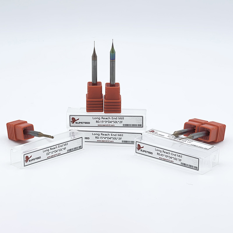
The engineered solution lies in reduced shank end mills. These specialized cutters balance the required extended reach with maximum tool rigidity. By localizing the cutting edge and relieving the non-cutting shank area, they provide the necessary clearance to navigate complex geometries. This design enables extreme precision in deep cavities without sacrificing cycle times, feed rates, or final part quality.
Understanding the precise geometry of these cutting tools dictates their performance under heavy radial loads on the shop floor. The anatomy of the tool is engineered specifically to fight the bending forces that plague deep pocketing operations. When you extend a tool out of the spindle, it acts as a cantilever beam. The longer the beam, the more it bends under pressure. We rely on specific geometric zones to counteract this physical limitation.
The design consists of four distinct geometric zones that work together to stabilize the cutting process:
Machinists often use terminology interchangeably, but clear distinctions exist. The term reduced neck end mills typically refers to tools featuring a short, localized relief immediately behind the cutting edge, designed for shallow undercuts or minor reach extensions. Conversely, a reduced shank implies a much longer relieved section extending significantly toward the tool holder, engineered specifically for deep cavity penetration.
The physics of rigidity govern the success of these tools. Tool deflection follows a cubic relationship with length. If you double the length of a tool, it deflects eight times as much under the same load. A standard long-flute end mill removes massive amounts of core material to create the flutes, severely weakening the cross-section. A shorter flute length combined with a relieved neck maximizes the solid carbide closer to the spindle. This geometry increases the moment of inertia. It resists bending forces drastically better than continuous long-flute end mills, keeping the cutting edge stable and on a true toolpath.
Deep cavity machining demands specialized approaches, particularly in industries where complex internal geometries dictate part function. Mold and die manufacturing relies heavily on these relieved tools. Machining core and cavity blocks requires reaching deep into hardened tool steels like P20 or H13. These molds often feature steep draft angles and vertical walls that extend several inches deep.
Standard tools rub against these walls, causing work hardening in the material and rapid tool failure. Relieved shanks navigate these deep drafts effortlessly. They ensure the cutting edge engages the material without catastrophic shank interference, allowing you to machine deep parting lines and ejector pin pockets with confidence.
Undercutting and recessed surface machining represent another primary application. Aerospace and medical components frequently feature internal features inaccessible by standard straight-shank tools. The relieved geometry allows the cutting edge to pass through narrow openings to machine wider internal cavities. Machinists frequently pair relieved shanks with specialized profiles, such as lollipop cutters or spherical end mills. This combination proves highly effective in simultaneous 5-axis setups, allowing the spindle to articulate around complex internal features without collision.
High-precision finishing at extended reaches requires absolute tool stability. When finishing deep walls, machinists deploy high-flute-count reduced shank tools. These tools take very light radial depths of cut. The high flute count allows for elevated feed rates while maintaining a low feed per tooth. The inherent rigidity of the relieved neck prevents the tool from pushing away from the wall. This stability ensures superior surface finish, eliminates witness marks, and guarantees tight dimensional accuracy across the entire depth of the cavity.
Typical Machining Parameters for Deep Cavity Applications
| Operation Type | Recommended Flute Count | Radial Depth of Cut (RDOC) | Axial Depth of Cut (ADOC) | Primary Goal |
|---|---|---|---|---|
| Deep Pocket Roughing | 2 to 3 Flutes | 5% to 10% of Diameter | Up to 2x Diameter | Maximum chip evacuation and material removal |
| Semi-Finishing Walls | 4 Flutes | 2% to 5% of Diameter | Up to 3x Diameter | Correcting geometry and reducing step-overs |
| High-Precision Finishing | 5 to 7 Flutes | 0.5% to 2% of Diameter | Full depth of feature | Mirror surface finish and tight tolerances |
| 5-Axis Undercutting | 4 Flutes (Spherical) | Variable based on CAM | Variable based on CAM | Navigating complex internal geometries |
Deploying specialized tooling involves evaluating specific performance metrics against operational constraints. Tool deflection and chatter reduction stand out as the primary mechanical advantages. When evaluating Length-to-Diameter (L/D) ratios, a standard long-flute tool at a 5:1 ratio will deflect significantly more than a relieved tool at the same overall reach. The relieved tool concentrates the cutting forces at the very tip, while the thicker upper shank absorbs the radial load. This structural advantage allows for more aggressive feed rates without the risk of dimensional deviation.
Surface finish quality directly correlates with tool rigidity. Harmonic vibration occurs when a cutting tool lacks the stiffness to resist the intermittent forces of milling. This vibration manifests as visible chatter marks on deep cavity walls, requiring extensive manual polishing bench-work later. Increased rigidity directly translates to dampened vibration. A stable cutting edge shears the material cleanly, leaving a mirror-like finish even at the bottom of a deep pocket.
Tool life and regrinding limitations present a distinct operational trade-off. Specialized relieved tools resist breakage and hold tight tolerances significantly longer than standard extended-reach tools. However, their complex geometry introduces maintenance challenges. If the cutting edge chips or wears heavily, regrinding becomes difficult or entirely impossible. Blending a new cutting edge into the existing relieved neck alters the tool's fundamental geometry and clearance capabilities. Therefore, upfront tool protection, rigid setups, and highly optimized CAM toolpaths become critical to maximizing tool life and justifying the initial investment.
Tool Geometry Comparison Matrix
| Feature | Standard Long-Flute End Mill | Reduced Shank End Mill |
|---|---|---|
| Wall Clearance | Poor (High risk of shank rubbing) | Excellent (Guaranteed clearance) |
| Tool Rigidity | Low (Prone to heavy deflection) | High (Maximized core diameter) |
| Surface Finish | Prone to chatter at extended reaches | Smooth, chatter-free finishes |
| Regrinding Capability | Standard (Easily reground) | Difficult (Geometry often compromised) |
| Ideal Application | Shallow profiling, peripheral milling | Deep pockets, mold walls, undercuts |
Selecting the correct relieved tool requires a systematic evaluation of the specific machining operation. Reach-to-Diameter (L/D) ratios dictate the baseline selection. Machinists must utilize a strict decision framework when determining optimal neck length. The golden rule of deep cavity machining is to choose the absolute shortest neck that still clears the cavity depth. Unnecessary reach invites unwanted vibration. If a cavity is two inches deep, selecting a tool with a three-inch reach sacrifices critical rigidity. Match the relieved length precisely to the required depth of the feature.
Flute count and cutting geometry must align with the intended operation. Low flute counts, typically two or three flutes, excel in deep pocket roughing. These tools provide massive flute valleys, maximizing chip clearance when evacuating material from confined spaces. Conversely, high flute counts of four or more are mandatory for finishing passes. Finishing prioritizes surface finish over material removal rates. High flute counts require light radial and axial cut depths to protect the fragile neck from excessive torque.
Profile selection heavily influences tool survivability. Adding a corner radius to a relieved tool significantly reduces the risk of corner chipping. Square profiles concentrate stress at the sharp corner, making them vulnerable in high-stress deep cavity environments. A corner radius distributes cutting forces across a larger surface area, extending tool life and preventing catastrophic edge failure during heavy engagement.
Coatings and substrates play a vital role in thermal management. Deep cavities restrict coolant access, leading to rapid heat buildup at the cutting zone. Material-specific coatings mitigate this thermal shock. Aluminum Titanium Nitride (AlTiN) excels in high-heat applications, forming a protective oxide layer that shields the carbide substrate. Titanium Carbonitride (TiCN) offers extreme hardness for abrasive materials. Selecting the correct coating ensures the cutting edge survives the harsh, unlubricated environment at the bottom of a deep pocket.
Executing deep cavity toolpaths introduces specific risks that require proactive mitigation. Tool breakage at the transition radius remains a primary failure mode. This failure stems from stress concentration at the exact point where the reduced neck meets the full shank. Heavy radial loads or sudden spikes in tool engagement exacerbate this stress, snapping the tool instantly. Mitigation requires advanced CAM programming. Utilize High-Efficiency Milling (HEM) or dynamic milling toolpaths. These strategies maintain a constant, light tool load by controlling the engagement angle. Ensure the CAM software generates smooth, arcing lead-ins and lead-outs to prevent shock loading the tool upon entry.
Poor chip evacuation destroys tools in deep pockets. Chips become trapped in deep, narrow cavities. The tool recuts these hardened chips, leading to rapid edge degradation and eventual tool failure. Mitigation demands aggressive chip management. Implement high-pressure through-spindle coolant to blast chips upward and out of the cavity. If machining materials that require dry cutting, such as certain tool steels, utilize high-velocity air blasts. Implement peck milling strategies or retract the tool periodically to allow chips to clear the cutting zone safely.
Excessive runout and handling damage compromise precision before the spindle even turns. Extended reach magnifies any runout present in the spindle taper or the tool holder. A thousandth of an inch of runout at the holder translates to massive deviation at the tip of a long-reach tool. Additionally, the relieved neck makes the tool physically fragile during handling, setup, and storage. Mitigation requires strict shop floor discipline.
To prevent runout and handling damage, follow this strict setup protocol:
Navigating the complexities of deep cavity machining requires abandoning standard tooling approaches. Relieved shank geometries are not general-purpose cutters. They represent a mandatory, specialized investment for deep pocketing and complex 5-axis applications where shank clearance and structural rigidity are fundamentally at odds. By localizing the cutting action and maximizing the shank diameter, these tools conquer the physical limitations of extended-reach milling.
Engineering and machining teams must audit their current deep cavity operations. Analyze scrap rates, document surface finish rejections, and track tool consumption in deep pockets. If standard long-flute tools are causing dimensional inaccuracies or requiring excessive manual polishing, the transition to relieved neck geometries is technically justified.
A: Reduced neck end mills feature a short, localized relief immediately behind the cutting flutes, primarily used for shallow undercuts. Reduced shank end mills have a much longer relieved section that extends significantly toward the tool holder, engineered specifically to provide clearance for deep cavity penetration.
A: Deflection depends on the Length-to-Diameter (L/D) ratio and cutting forces. While standard tools struggle past a 3:1 ratio, reduced shank tools can successfully machine at 5:1, 8:1, or even 10:1 ratios. Success at extreme depths requires very light radial depths of cut and dynamic milling strategies.
A: Yes. Extended reach magnifies runout exponentially. Standard collet chucks often lack the necessary concentricity. Machinists must use high-precision holders like shrink fit or hydraulic chucks to keep Total Indicator Runout (TIR) near zero, preventing premature tool wear and chatter.
A: Prevent chatter by maximizing rigidity. Choose the shortest possible neck length for the cavity. Use a high-precision tool holder. Program light radial depths of cut (RDOC) and utilize High-Efficiency Milling (HEM) toolpaths to maintain a constant, low cutting force.
A: They are not designed for traditional heavy roughing with large axial and radial engagements. The relieved neck creates a structural weak point under heavy torque. Instead, they should be used with dynamic roughing techniques, taking deep axial cuts but extremely light radial step-overs.
A: A high flute count, typically four to six flutes, is ideal for finishing. More flutes allow for a higher feed rate while maintaining a low feed per tooth. This reduces radial pressure on the extended neck and generates a superior surface finish on deep walls.