- All
- Product Name
- Product Keyword
- Product Model
- Product Summary
- Product Description
- Multi Field Search

Views: 0 Author: Site Editor Publish Time: 2026-08-07 Origin: Site
Deep cavity and pocket milling forces machinists to fight tool deflection, aggressive chatter, and poor surface finish. A frequent mistake on the shop floor involves grabbing a long flute end mill when the job only requires extended reach. This geometric mismatch kills core strength. It leads directly to snapped tools, scrapped parts, and blown cycle times. You must match the exact length of cut (LOC) and neck relief to the specific operation. The decision to specify long reach end mills comes down to balancing required physical access with maximum system rigidity. Specifying the correct tool geometry ensures the cutter survives the pass while holding tight tolerances. Understanding exactly when to deploy this specialized tooling turns unpredictable deep pocket operations into stable, repeatable processes.
Selecting the right tool for deep features requires a strict understanding of cutting tool anatomy. Machinists frequently confuse long length tools with long reach tools. While both offer extended overall lengths, their structural designs serve entirely different machining strategies. Using the wrong one guarantees poor performance.
Long length end mills feature flutes that extend across the majority of the tool's overall length. Tool manufacturers design these cutters specifically for machining deep, continuous walls or executing deep slotting operations where the entire flute length engages the material simultaneously. Engaging a massive axial depth of cut requires continuous chip evacuation channels along the entire contact area. However, this extended fluted section removes a massive amount of solid carbide from the tool's core. The lack of core material makes long length end mills highly susceptible to deflection and chatter when pushed hard. They act like weak springs under heavy lateral loads.
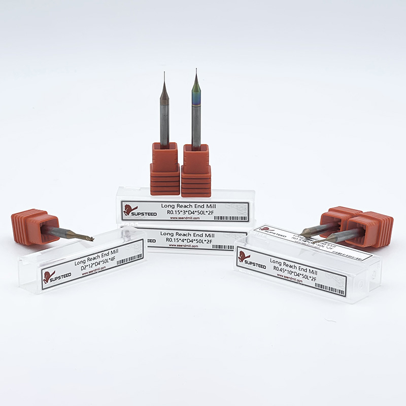
In contrast, long reach tools feature a very short length of cut (LOC) followed by a relieved neck. This neck diameter is ground slightly smaller than the cutting diameter, providing clearance as the tool descends into a pocket. The flutes stop immediately after the short cutting section. The remaining extended length consists of solid, un-fluted carbide extending back to the shank. This design isolates the cutting action to the very tip of the tool while maximizing the structural mass behind it.
The structural difference between a fluted section and a solid neck dictates the tool's performance. A solid carbide mass provides exponentially higher core strength and stiffness compared to a fluted section of the exact same length. Flutes act as structural weak points. When cutting forces apply lateral pressure against the tool tip, a fluted cylinder bends significantly more than a solid cylinder. By restricting the flutes only to the necessary cutting depth, long reach tools maximize the solid carbide cross-section. This geometry dramatically reduces tool deflection, mitigates chatter, and extends tool life during deep pocketing operations.
Tool Geometry Decision Matrix
| Machining Requirement | Recommended Tool Geometry | Primary Advantage |
|---|---|---|
| Deep reach with shallow axial step-downs | Long Reach End Mill | Maximum core rigidity and minimal deflection |
| Massive single-pass axial depth of cut | Long Length End Mill | Full-depth wall contact without step lines |
| Deep slotting with full flute engagement | Long Length End Mill | Continuous chip evacuation channels |
| Rest machining in deep pocket corners | Long Reach End Mill | Clearance for toolholder above the cavity |
Executing deep pocket operations successfully demands strict control over the machining environment. Extended overhangs magnify every minor flaw in your setup. You must evaluate clearance, deflection limits, and chip evacuation before generating the first toolpath. Ignoring these variables leads to immediate tool breakage.
The primary reason to specify extended reach tooling is to prevent catastrophic collisions. You must calculate the exact clearance required between the spindle nose, the toolholder face, and the top of the workpiece or fixture. Modern CAM software handles collision detection, but programmers must input accurate toolholder models. A standard ER collet chuck often features a wide nose nut that easily clips the upper walls of a deep cavity. Extended reach tools push the cutting edge deep into the part while keeping the bulky toolholder safely above the interference zone.
Follow this strict sequence to verify clearance:
Tool deflection remains the absolute enemy of deep pocket milling. The length-to-diameter (L:D) ratio dictates the severity of this deflection. Machining physics dictates that tool deflection increases as a cube of the overhang length. If you double the extended length of a tool, it does not deflect twice as much; it deflects eight times as much under the same cutting pressure. Managing this exponential loss of rigidity requires precise control over radial engagement and feed rates.
The base diameter of the cutting tool fundamentally changes how you handle the L:D ratio. A 4-inch reach on a 1-inch diameter end mill yields a 4:1 ratio. This setup remains highly manageable and can handle aggressive roughing parameters. Conversely, a 4-inch reach on a 1/4-inch diameter end mill creates a severe 16:1 ratio. This extreme overhang requires specialized programming, micro-machining parameters, and hyper-conservative entry strategies. You cannot scale feeds and speeds linearly across different diameters when dealing with extended reach.
Deep pockets act as traps for metal chips. If chips fail to evacuate the cavity, the cutter will recut them. Chip recutting destroys the cutting edges instantly, especially on micrograin carbide tools. Tool geometry heavily impacts chip flow. Because long reach tools have short flutes, chips must eject completely out of the cutting zone before they pack around the relieved neck. High-pressure air blasts or through-spindle coolant become mandatory to blast chips upward and out of the pocket.
Lack of rigidity directly causes chatter. Chatter manifests as harmonic vibrations that leave visible, unacceptable resonance patterns on the pocket walls and floor. Beyond aesthetics, chatter destroys dimensional accuracy and rapidly chips the cutting edge. Maintaining a pristine surface finish at the bottom of a deep cavity requires stabilizing the tool through light radial cuts, elevated spindle speeds, and rigid toolholding.
Recognizing the exact scenarios that demand extended reach tooling prevents wasted time and broken cutters. These tools excel in specific applications where standard end mills fail to provide necessary access. You must identify these situations early in the programming phase.
Mold making and aerospace component manufacturing frequently require deep, localized pockets. These cavities often feature complex floor geometries that require finishing without long continuous wall contact. Long reach tools allow the programmer to step down into the cavity using dynamic milling toolpaths. The short length of cut handles the light axial engagement, while the relieved neck provides the necessary clearance against the upper draft angles of the mold base.
Many shops operate 3-axis vertical machining centers without the capability to tilt the spindle or the table. When a 5-axis setup isn't available or practical, accessing undercut or deep-set features becomes a severe challenge. Extended reach tooling bridges this gap. It allows a standard 3-axis machine to reach down into complex geometries, bypassing upper obstructions like tall bosses or clamps that would otherwise require multiple setups or specialized angle heads.
Machining internal steps, bosses, or islands at the bottom of a deep bore requires precision access. Once a larger roughing tool clears the upper walls of the main bore, you need a smaller tool to machine the intricate floor features. A standard toolholder would crash into the bore walls. A long reach tool drops into the cleared bore, keeping the holder safely above the part, and machines the internal steps using its short cutting edge.
Large indexable cutters or high-feed mills excel at hogging out massive volumes of material in deep pockets. However, they leave large radii in the internal corners. Rest machining involves coming back into that deep pocket with a smaller diameter tool to pick out those tight corner radii. A long reach tool is the perfect candidate for this operation. It provides the small cutting diameter needed for the tight corners while offering the extended neck required to reach the bottom of the previously roughed cavity.
Standard extended reach tools handle most deep pocket applications. However, certain extreme geometries push machining capabilities to their absolute limits, requiring specialized tooling and ultra-conservative strategies. You cannot treat these extreme tools like standard end mills.
The machining industry generally defines standard reach as anything up to a 5:1 length-to-diameter ratio. Once you cross this threshold, you enter the territory of extra long reach end mills. These tools feature L:D ratios ranging from 5:1 up to 10:1, and sometimes even higher for specialized micro-machining applications. Operating in this zone completely changes the physics of the cut. Deflection becomes the dominant variable in every toolpath calculation.
Extra long reach tools dominate niche manufacturing sectors. Automotive manufacturers use them for deep water jacket machining in engine blocks. Aerospace shops deploy them for complex manifold internal porting where fluid dynamics require smooth internal finishes deep inside a block. Extreme mold cavities, particularly those for large plastic injection parts, also demand these tools to reach the deepest draft angles without colliding with the massive mold base.
Machining with extra long reach tools introduces an exponential risk of catastrophic tool failure. You cannot use standard cutting data. These applications require hyper-conservative machining parameters. You must minimize the radial depth of cut (RDOC) to micro-machining levels, often engaging less than 5% of the tool's diameter. This razor-thin engagement reduces tool pressure, prevents the cutter from bending, and keeps heat generation to an absolute minimum.
To combat the extreme loss of rigidity at high L:D ratios, tooling engineers developed tapered neck long reach end mills. Instead of a straight cylindrical neck, the neck gradually tapers outward from the cutting diameter back to the shank. This taper adds critical mass and structural rigidity to the tool while still providing necessary clearance against drafted pocket walls. When pushing past a 7:1 ratio, a tapered neck often becomes the only viable solution to prevent aggressive chatter.
Implementing extended reach tooling requires a thorough technical evaluation of your entire machining process. You must adjust feeds, evaluate materials, and understand the lifecycle of the tool to maintain profitability. Guessing at parameters will destroy the tool on the first pass.
You must aggressively derate standard feeds and speeds when using extended reach tools. Never rely on generic cutting charts. Calculate the reduction based on the specific overhang length. As a general rule, for every increment above a 3:1 L:D ratio, you must reduce the feed per tooth and adjust the surface footage to prevent harmonic vibration. Consult manufacturer-specific cutting data that explicitly accounts for extended reach. Pushing these tools at standard parameters guarantees instant failure.
L:D Ratio Derating Guidelines
| L:D Ratio | Feed Reduction | Speed Reduction | Strategy Adjustment |
|---|---|---|---|
| Up to 3:1 | 0% (Standard) | 0% (Standard) | Standard dynamic milling |
| 4:1 to 5:1 | Reduce by 20% | Reduce by 15% | Decrease RDOC by 10% |
| 6:1 to 7:1 | Reduce by 40% | Reduce by 30% | Decrease RDOC by 25%, use air blast |
| 8:1 and above | Reduce by 60%+ | Reduce by 50%+ | Micro-machining RDOC, tapered neck required |
The workpiece material dictates the viability and strategy of extended reach machining. Soft materials like 1018 steel, 6061 aluminum, or brass are relatively forgiving. They generate lower cutting forces, allowing you to push longer tools with moderate success. Conversely, machining Inconel, Titanium, or hardened tool steels with extended reach tools presents extreme difficulty. These high-temp alloys generate massive tool pressure and heat. Cutting them at extended lengths requires absolute rigidity, premium coatings, and flawless toolpath execution.
When tool rigidity is compromised by length, the quality of the carbide substrate and the coating becomes a critical investment. Ultra-fine micrograin carbide provides the necessary transverse rupture strength to withstand lateral bending forces without snapping. Advanced PVD and CVD coatings protect the cutting edge from thermal breakdown. Because you must take lighter cuts, the tool spends more time rubbing in the cut. Premium coatings provide the lubricity needed to prevent built-up edge (BUE) during these extended cycle times.
Tool lifecycle management becomes complicated with extended reach tools. Resharpening alters the tool's outer diameter and potentially reduces its overall length. When you grind the flutes, the cutting diameter shrinks, but the solid neck diameter remains the same. If the cutting diameter becomes smaller than the neck diameter, the neck will rub against the pocket walls, causing massive friction and tool failure. You must implement strict CAM updates to account for the altered geometry and ensure the relieved neck still clears the workpiece.
Hardware alone will not solve deep pocket challenges. You must pair the correct tool geometry with modern toolpath strategies and premium toolholding to achieve success. A great tool in a bad holder with a poor toolpath will still break.
High-Efficiency Milling (HEM) or dynamic milling toolpaths are mandatory for long reach applications. Traditional offset roughing buries the tool in internal corners, causing massive spikes in tool pressure that instantly snap extended necks. HEM maintains a low, constant radial engagement throughout the entire toolpath. By taking very light radial cuts at higher feed rates, HEM directs the cutting forces axially up into the spindle rather than laterally against the weak neck of the tool.
Never plunge a long reach tool directly into solid material. Plunging directs 100% of the force directly up the Z-axis, but any slight runout will cause the long neck to buckle and snap. Always use helical interpolation or ramping strategies to enter deep pockets. Keep the ramp angle very shallow, typically between 0.5 and 1.5 degrees. This gradual entry minimizes tool pressure and allows the short flutes to evacuate chips effectively before full axial engagement.
Standard ER collets are often insufficient for long reach applications. ER collets inherently introduce total indicator runout (TIR). At a 2-inch extension, a minor runout at the collet face might be acceptable. At a 6-inch extension, that same runout magnifies exponentially, causing the tool tip to whip aggressively. This whipping destroys the cutting edge and creates massive chatter. You must upgrade to shrink-fit holders, hydraulic chucks, or precision milling chucks. These premium holders maximize gripping force and keep TIR to an absolute minimum.
Deep pockets create a vacuum that traps chips. If you use flood coolant, the fluid often fails to reach the bottom of the cavity, instead creating a slurry of recut chips that destroys the tool. Evaluate the use of high-pressure through-spindle coolant if your machine and tool support it. If not, programmable high-pressure air blasts are often superior to flood coolant for deep pocketing. Air evacuates the chips violently upward without creating a sticky slurry, ensuring the cutter always engages clean material.
To successfully implement these tools in your next deep pocket operation, execute the following steps:
A: Length of cut (LOC) refers strictly to the fluted cutting portion of the end mill. Reach defines the total distance from the face of the toolholder to the tip of the tool. On a long reach end mill, the reach includes both the short fluted section and the extended, un-fluted solid neck.
A: Reduce chatter by drastically decreasing your radial depth of cut (RDOC). Maintain a constant tool load using dynamic milling toolpaths. Slightly increase your feed per tooth to stabilize the cutter and prevent rubbing. Finally, ensure minimal runout by using premium shrink-fit or hydraulic toolholders.
A: Profiling deep walls with a long reach end mill is a poor choice. The short LOC requires multiple axial step-downs, which will leave visible step-lines on the finished wall. For deep, continuous wall profiling, use a long length end mill to engage the entire wall in a single pass.
A: Standard machining limits usually sit around a 3:1 to 5:1 L:D ratio. Extra long reach applications can push this to 10:1 or higher depending on the base diameter. Ratios exceeding 5:1 require extreme precautions, micro-machining parameters, and perfectly rigid setups to prevent tool failure.
A: Climb milling remains the preferred method for chip evacuation and heat management. However, climb milling naturally pulls the cutter into the workpiece. With extended reach tools, this deflection can cause overcutting. You must take very light radial passes to minimize this pull while maintaining the benefits of climb milling.
A: Yes. Standard collet chucks introduce too much runout, which magnifies exponentially over an extended reach. You must use high-precision toolholders like shrink-fit or hydraulic chucks. These holders eliminate runout, provide maximum concentricity, and prevent the tool tip from whipping during the cut.