- All
- Product Name
- Product Keyword
- Product Model
- Product Summary
- Product Description
- Multi Field Search

Views: 0 Author: Site Editor Publish Time: 2026-08-14 Origin: Site

Machining highly abrasive materials like graphite, carbon-fiber-reinforced polymers (CFRP), and fiberglass rapidly degrades standard carbide tooling. This rapid wear leads to unacceptable dimensional variance and surface finish degradation on the shop floor. Selecting the wrong tooling for these abrasive composites results in premature tool failure. You face increased machine downtime, high scrap rates on expensive raw materials, and an inflated cost-per-part. Optimizing production requires a strict technical evaluation of the two primary solutions for abrasive machining: diamond coated end mills and PCD end mills. We will break down the structural differences, performance trade-offs, and application-specific criteria for both. You need reliable data to keep spindles turning and maintain tight tolerances across long production runs.
Machining abrasive materials requires a precise balance between cutting edge sharpness and extreme wear resistance. You must define baseline requirements for material removal without compromising part integrity. Success in these applications means achieving tight dimensional tolerances, maintaining a clean surface finish, and preventing structural damage to the workpiece. Graphite and composite materials present unique mechanical challenges that rapidly destroy conventional cutting tools.
Standard uncoated or PVD-coated micro-grain carbide fails quickly when exposed to the silica or carbon fibers found in advanced composites. These fibers act like microscopic abrasive grains. As the tool rotates, the fibers constantly grind against the cutting edge. Standard carbide lacks the necessary hardness to withstand this continuous abrasion. The cutting edge rounds off in a matter of minutes. Once the edge dulls, cutting forces increase exponentially, generating excessive heat and pushing the material rather than shearing it cleanly.
In CFRP applications, dull cutting edges lead directly to mechanical delamination. When the tool fails to slice through the carbon fibers, it pulls and drags them. This pulling action separates the individual composite layers, causing fiber pull-out and leaving uncut fibers along the machined edge. Fraying compromises the structural integrity of the aerospace or automotive component, often resulting in immediate part rejection. Maintaining a razor-sharp edge is an absolute requirement to shear composite fibers effectively.
Graphite machining presents a different mechanical challenge focused on dust evacuation. Graphite does not form chips; it shatters into a highly abrasive fine powder. If this dust is not immediately evacuated from the cutting zone, it packs into the tool flutes. The trapped dust acts as a lapping compound, aggressively grinding away the tool material with every spindle revolution. Specialized flute geometries with deep valleys and specific helix angles are necessary to pump this abrasive dust away from the cutting edge and out of the machining envelope.
Common Failure Modes of Standard Carbide in Composites
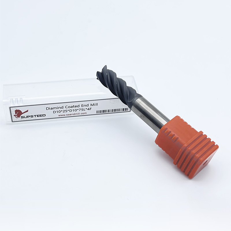
A diamond coated end mill consists of a micro-grain tungsten carbide substrate enveloped by a crystalline diamond layer. Manufacturers apply this layer using a Chemical Vapor Deposition (CVD) process. The CVD process grows real diamond crystals directly onto the carbide surface in a high-temperature vacuum chamber. This creates a continuous, highly wear-resistant barrier that protects the relatively softer carbide core from abrasive workpiece materials.
You must distinguish between true CVD diamond coatings and Diamond-Like Carbon (DLC) coatings or standard Physical Vapor Deposition (PVD) coatings. True CVD diamond offers five to ten times higher wear resistance than standard PVD options. DLC coatings provide excellent lubricity and work well for less abrasive synthetics and soft plastics. However, DLC lacks the extreme hardness required for pure graphite or aerospace-grade CFRP. For highly abrasive environments, only a true CVD grown diamond structure provides the necessary tool life.
The primary advantage of the CVD process is its geometric flexibility. Because the coating grows uniformly over the tool, manufacturers can apply it to complex, multi-flute, and high-helix geometries. This allows for the creation of specialized ball nose and corner radius tools ideal for intricate 3D profiling and complex mold making. Additionally, the solid carbide core provides superior vibration dampening compared to brazed tools. The solid substrate absorbs cutting harmonics, resulting in smoother surface finishes on complex 3D contours.
Despite these advantages, CVD coatings have inherent limitations regarding edge sharpness. There is a direct trade-off between coating thickness and cutting edge radius. Thinner coatings retain a sharper edge, which helps shear softer plastics cleanly, but they sacrifice long-term wear resistance. Thicker coatings provide maximum abrasion resistance but inherently increase edge rounding. This slightly reduces the absolute sharpness of the cutting edge, which can increase cutting forces. Furthermore, coating adhesion remains a risk. If the carbide substrate preparation is suboptimal, or if cutting temperatures exceed the coating's thermal limits, the diamond layer can delaminate and flake off, leading to immediate tool failure.
Coating Technology Comparison
| Coating Type | Application Method | Hardness (HV) | Best Application |
|---|---|---|---|
| True CVD Diamond | Chemical Vapor Deposition | 8,000 - 10,000 | Graphite, CFRP, Ceramics |
| DLC (Diamond-Like Carbon) | Physical Vapor Deposition | 2,000 - 4,000 | Aluminum, Soft Plastics |
| TiAlN (Standard) | Physical Vapor Deposition | 3,000 - 3,500 | Steels, Cast Iron |
Polycrystalline Diamond (PCD) tooling represents a completely different manufacturing approach. A PCD end mill consists of synthetic diamond wafers brazed directly onto a solid carbide or steel tool body. Manufacturers create these wafers by sintering diamond particles together under extreme pressure and temperature with a metallic binder. The resulting diamond blank is then cut to shape using electrical discharge machining (EDM) and brazed into pockets milled into the tool body.
The structural characteristics of PCD provide significant advantages for specific applications. The polycrystalline diamond layer is substantially thicker than any CVD coating. This massive diamond structure delivers extreme hardness and a higher maximum working temperature. The structural rigidity of the thick diamond wafer allows it to withstand continuous, aggressive abrasion far longer than a thin coating. The diamond volume simply outlasts coated alternatives in high-volume production runs.
PCD tools offer unmatched abrasion resistance in continuous cutting applications. Because the diamond layer is thick, manufacturers can grind the cutting edge to a razor-sharp profile using specialized diamond wheels. This allows the tool to maintain an incredibly sharp cutting edge for an extended period, minimizing composite fraying without the edge-rounding penalty associated with thick CVD coatings. Furthermore, the thick diamond wafer provides the potential for multiple regrinds or re-tipping. When the edge finally dulls, the tool can be sent back to the manufacturer to be sharpened, significantly extending the lifecycle of the tool body.
However, the brazed wafer design introduces severe geometrical constraints. PCD end mills are typically limited to straight flutes or very low shear angles. You cannot easily manufacture a high-helix or complex 3D ball nose profile with brazed flat wafers. Additionally, the polycrystalline diamond structure is extremely brittle. This brittleness makes PCD tools highly susceptible to impact damage. They are entirely unsuitable for unstable machining setups, loose fixtures, or heavy interrupted cuts. Any sudden shock or vibration will chip or shatter the diamond wafer instantly.
Setup Requirements for PCD Tooling
Selecting the correct tool requires evaluating how each technology interacts with your specific part geometry, machine capabilities, and workpiece material. A direct comparison across critical performance dimensions reveals where each tool excels and where it fails.
Tool geometry dictates the types of features you can machine. Coated solid carbide offers exceptional multi-axis profiling capabilities. You can utilize five-flute, high-helix designs to achieve high feed rates and superior surface finishes on complex 3D contours. The solid carbide substrate allows for intricate ball nose and corner rounding profiles. In contrast, PCD tools feature rigid, limited-flute designs. The brazing process restricts them to one, two, or occasionally three straight or slightly angled flutes. If your part requires deep 3D contouring, solid carbide is the only practical choice. For flat 2D routing, PCD geometry is perfectly adequate.
The interaction between sharpness and wear resistance defines tool life in composites. A ground PCD edge achieves an exceptionally high initial sharpness and retains that sharpness over a massive volume of material due to the thick diamond layer. This makes it superior for shearing carbon fibers cleanly over long production runs. A CVD diamond coated tool has a slightly rounded edge due to the coating buildup. While highly uniform and extremely hard, it cannot match the sheer slicing ability of a freshly ground PCD edge. However, the coated edge is less prone to micro-chipping under variable loads.
Substrate survivability is critical in real-world machining. The tougher microstructures of solid carbide substrates allow coated tools to handle harmonic vibrations significantly better than brazed tools. When milling across cross-holes, slots, or uneven composite layups, the tool experiences interrupted cutting. These repeated impacts will quickly shatter a brittle PCD insert. Solid carbide absorbs these shocks, keeping the cutting edge intact. If your toolpath involves heavy interruptions or your fixturing lacks absolute rigidity, you must utilize solid carbide to prevent catastrophic tool failure.
Heat generation destroys cutting tools. PCD end mills possess higher heat tolerance and superior thermal conductivity compared to coated carbide. The thick diamond wafer pulls heat away from the cutting edge efficiently. CVD coatings have strict thermal limitations; excessive heat causes the cobalt in the carbide substrate to expand, leading to coating delamination. This thermal dynamic dictates your machining strategy. PCD can often run dry at higher surface speeds in composites, while coated tools may require careful speed management or air blasts to prevent thermal degradation of the coating bond.
Material properties ultimately drive tool selection. For graphite electrode machining, coated tools are universally preferred. Graphite electrodes require intricate details, thin ribs, and complex 3D shapes that demand the geometric flexibility of solid carbide. The continuous abrasion of graphite dust is perfectly managed by the hard CVD layer. Conversely, PCD dominates the composite industry. For straight-line routing, trimming, and facing of large CFRP panels, the continuous cutting action and need for extreme edge sharpness make PCD the undisputed standard.
Tooling Comparison: Diamond Coated vs. PCD
| Feature | Diamond Coated Solid Carbide | Polycrystalline Diamond (PCD) |
|---|---|---|
| Wear Resistance | High (Surface Level) | Extreme (Structural Level) |
| Edge Sharpness | Slightly Rounded (Coating Build-up) | Razor Sharp (Ground Edge) |
| Geometry Flexibility | Excellent (3D Profiling, High Helix) | Limited (Straight Flute, Low Shear) |
| Impact Tolerance | Moderate (Absorbs Harmonics) | Very Low (Highly Brittle) |
| Primary Application | Graphite Electrodes, 3D Contouring | CFRP Routing, 2D Facing |
Evaluating the true financial impact of your tooling requires a framework that looks beyond the initial acquisition investment. You must calculate the return based on production output, machine uptime, and part quality. The most accurate metric for abrasive machining is derived from the expected linear inches cut before tool failure.
When comparing initial tool investments, coated solid carbide presents a lower upfront barrier. This makes it attractive for short production runs, prototyping, or shops with limited capital budgets. However, you must map this initial investment against the expected linear inches cut. A coated tool may require less capital initially but might only complete a fraction of the linear inches before the coating breaches and the tool fails. In high-volume scenarios, the higher initial investment of a brazed diamond tool rapidly pays for itself through massively extended uninterrupted run times and reduced tool changeovers.
Tool reconditioning realities drastically alter the long-term value equation. Coated tools are generally considered disposable. Once the diamond layer breaches and the carbide substrate wears, the tool geometry is lost. Stripping the remaining diamond and recoating the tool is rarely practical or dimensionally accurate. You consume the tool and discard it. In contrast, the regrinding and re-tipping lifecycle of brazed tools is a primary factor in long-term production efficiency. A thick diamond wafer can often be resharpened two to four times. You pay a fraction of the new tool investment for a regrind, effectively resetting the tool life and driving the cost-per-part down significantly over high-volume production cycles.
Even the highest quality tooling will fail prematurely if implemented incorrectly. You must address the operational hazards specific to abrasive machining to maximize tool life and protect your workpiece. Both tool categories carry unique implementation risks that require strict mitigation strategies on the shop floor.
Mitigating coating delamination is the primary concern when running coated solid carbide. Excessive heat buildup is the enemy of coating adhesion. You must optimize your feeds and speeds to ensure the chip load is thick enough to carry heat away from the tool, rather than rubbing and generating friction. If the cutting temperature exceeds the maximum working temperature of the CVD bond, the coating will flake off. Maintain aggressive feed rates to keep the tool cutting efficiently, and utilize high-pressure air blasts to clear abrasive dust instantly, preventing it from generating secondary friction in the cut.
Preventing brittle failure is the absolute priority when running brazed diamond tools. The extreme hardness of the diamond wafer makes it highly susceptible to chipping. Machine rigidity is non-negotiable. Your spindle runout tolerances must be minimal. Excessive runout causes uneven chip loads, forcing one diamond flute to take the entire cutting force, which leads to immediate micro-chipping. You must also program your toolpaths to avoid heavy interrupted cuts. Enter the material using smooth ramping or helical interpolation rather than aggressive plunging, and ensure your workholding fixtures prevent any material vibration during the cut.
Coolant and evacuation considerations vary drastically based on the material. When machining graphite, you must run completely dry. Introducing liquid coolant to graphite dust creates an abrasive sludge that packs into the flutes and destroys the machine's guideways. You must implement high-velocity vacuum dust extraction systems directly at the spindle. For composites like CFRP, dry machining with strong vacuum extraction is also common to prevent airborne fibers. However, in certain thick composite applications, specialized flood coolant can be used to manage heat, provided the machine filtration system is equipped to handle fine carbon particulate without clogging. Always match your evacuation strategy to the specific material to prevent tool packing and thermal shock.
Troubleshooting Common Machining Issues
| Symptom | Probable Cause | Corrective Action |
|---|---|---|
| CFRP Delamination | Dull cutting edge or low feed rate | Switch to a sharper tool; increase feed per tooth. |
| Coating Flaking | Excessive heat generation | Increase air blast; verify chip load is sufficient. |
| PCD Edge Chipping | Spindle runout or interrupted cut | Check toolholder concentricity; adjust toolpath entry. |
| Poor Surface Finish | Vibration or harmonic chatter | Increase fixture rigidity; reduce spindle speed slightly. |
A: Chemical Vapor Deposition (CVD) grows real diamond crystals directly onto the tool, providing extreme hardness and high wear resistance suitable for pure graphite. Diamond-Like Carbon (DLC) is a thinner, less hard PVD coating that offers high lubricity. DLC works well for softer synthetics and aluminum but degrades rapidly in highly abrasive materials like aerospace CFRP.
A: There is an inverse relationship between coating thickness and cutting edge sharpness. As the CVD coating builds up on the carbide substrate, it naturally rounds the cutting edge. Thicker coatings provide maximum abrasion resistance but reduce the tool's ability to shear materials cleanly. Thinner coatings maintain a sharper edge but wear out faster.
A: No, it is generally not practical to regrind them. Once the coating breaches and the carbide substrate wears, the original geometry is lost. Stripping the remaining diamond and applying a new CVD layer results in dimensional inaccuracies. They are considered disposable.
A: They rely on flat, synthetic diamond wafers brazed into pockets on the tool body. The physical size of these wafers and the required brazing area limit the geometric flexibility. It is extremely difficult to braze multiple wafers into a tight, high-helix configuration, restricting them primarily to one or two straight flutes.
A: While they can cut these materials, they are not optimal. The slightly rounded edge from the thick CVD coating can cause smearing or melting in soft plastics and gummy aluminum. Uncoated polished carbide or DLC-coated tools with razor-sharp edges perform much better in non-abrasive, soft materials.
A: Tool runout is catastrophic for brazed diamond tools. Because the polycrystalline diamond layer is extremely brittle, uneven cutting forces caused by runout will overload a single flute. This uneven chip load causes immediate micro-chipping and rapid failure of the diamond edge. Spindle runout must be kept to an absolute minimum.
A: Brazed diamond tools are generally superior for preventing delamination in high-volume CFRP routing. Their thick diamond layer can be ground to a razor-sharp edge that cleanly shears the carbon fibers without pulling them. They maintain this extreme sharpness significantly longer than coated tools, preventing the dulling that causes mechanical delamination.