- All
- Product Name
- Product Keyword
- Product Model
- Product Summary
- Product Description
- Multi Field Search

Views: 0 Author: Site Editor Publish Time: 2026-08-19 Origin: Site

Machine rigidity has a direct effect on milling tool performance. A rigid machine setup allows the cutting edge to engage the workpiece more predictably. A weak setup allows vibration, tool deflection and unstable chip load to increase. The same milling tool may perform well on a stable machine but wear quickly, chatter or produce poor surface finish on a less rigid setup.
When machine rigidity is limited, choosing the right Milling Tools becomes more important because tool geometry, overhang, carbide grade and cutting strategy all affect machining stability.
In milling, the tool does not work alone. It is part of a complete rigidity chain that includes the machine frame, spindle, tool holder, cutting tool, workholding and workpiece. If one part of this chain is weak, milling tool performance can decline even when the tool itself is high quality.
This article explains how machine rigidity affects chatter, tool deflection, surface finish, dimensional accuracy, tool wear and tool life. It also explains how buyers can adjust milling tool selection and cutting parameters when machine rigidity is not ideal.
Machine rigidity affects milling tools by controlling vibration, tool deflection, chip load stability, surface finish, dimensional accuracy and tool life.
Key points include:
Low rigidity increases milling tool vibration.
Weak setups make chatter more likely.
Longer tool overhang increases deflection risk.
Poor workholding can cause dimensional error.
Unstable chip load can accelerate edge wear.
Edge chipping often increases when impact load is unstable.
A rigid setup allows more consistent cutting performance.
Less rigid machines often require conservative cutting parameters.
Tool holder condition affects runout and cutting stability.
Carbide milling tools must be matched with the machine, material, overhang and toolpath.
A high-quality tool can improve cutting stability, but it cannot fully compensate for weak machine rigidity, poor clamping or excessive tool overhang.
Machine Rigidity → Vibration Control → Tool Deflection → Cutting Stability → Surface Finish → Tool Life
Machine rigidity in milling refers to the stiffness of the complete machining system. It is not only the machine body. It includes every part that resists cutting force during machining.
A typical rigidity chain can be shown as:
Machine Frame → Spindle → Tool Holder → Milling Tool → Workholding → Workpiece
If the machine frame is weak, the structure may vibrate under load. If the spindle is worn or unstable, the cutting tool may not rotate accurately. If the tool holder has runout, each cutting edge may not share the load evenly. If the workholding is weak, the workpiece may move during cutting.
This means milling tool performance depends on both tool quality and setup quality. A strong carbide end mill still needs a rigid machine, proper holder, short overhang and stable workholding to perform close to its designed capability.
Milling tools remove material through repeated cutting edge engagement. Each flute enters and exits the workpiece, creating changing cutting forces. A rigid setup can resist these forces and keep the cutting process stable.
When rigidity is good, milling tools can usually deliver:
more stable chip formation;
better surface finish;
more accurate dimensions;
lower chatter risk;
more predictable tool wear;
better tool life;
higher cutting confidence;
more stable roughing and finishing.
When rigidity is poor, the cutting edge may not stay in the intended position. This can create vibration, deflection and uneven cutting load. In some cases, the operator must reduce feed, axial depth of cut or radial depth of cut to prevent tool damage.
Machine rigidity therefore affects not only quality, but also productivity.
Chatter is one of the most common signs of low rigidity in milling. It often appears as loud noise, visible vibration, uneven cutting marks or repeated wave patterns on the machined surface.
Low rigidity can allow vibration to grow during cutting. As the tool vibrates, the chip thickness changes from one flute engagement to the next. This creates unstable cutting force. The unstable force then increases vibration further.
The result may include:
chatter marks on the workpiece;
poor surface finish;
cutting noise;
unstable tool load;
shortened tool life;
edge chipping;
lower material removal rate;
reduced machining confidence.
Milling tool chatter is not always caused by the tool itself. It may come from weak workholding, excessive tool overhang, poor holder condition, worn spindle components, thin workpiece walls or unsuitable cutting parameters.
Tool deflection occurs when the milling tool bends under cutting force. Every tool can deflect to some degree, but deflection becomes more serious when the setup is weak, the tool is long, the diameter is small or the cutting force is high.
A simple relationship can be shown as:
Higher Cutting Force + Longer Overhang + Lower Rigidity → More Tool Deflection
Milling tool deflection may cause:
tapered walls;
dimensional error;
oversize or undersize features;
poor slot accuracy;
uneven tool wear;
poor corner quality;
tool rubbing;
vibration;
edge damage.
Tool overhang in milling is especially important. A longer overhang reduces stiffness and increases bending risk. This is why deep pocket machining, side wall machining and long-reach applications need careful tool selection.
When long reach is unavoidable, the tool should be selected with attention to neck design, flute length, core strength, diameter and cutting parameters.
Surface finish is often the first visible sign of rigidity problems. When a machine setup is stable, the tool follows a more consistent path. When rigidity is poor, vibration and deflection leave marks on the workpiece.
Poor rigidity may cause:
chatter marks;
uneven surface texture;
waviness;
poor wall straightness;
inaccurate dimensions;
poor corner finish;
inconsistent finishing results.
Dimensional accuracy also depends on cutting stability. If the tool deflects during roughing, the remaining stock may not be uniform. If the tool vibrates during finishing, the final surface may not meet the required tolerance.
A rigid milling setup allows carbide milling tools to cut more predictably. This is especially important for mold machining, precision components, aerospace parts, medical parts and hardened steel finishing.
Tool wear is affected by heat, cutting force, material hardness, coating, chip evacuation and setup stability. When machine rigidity is poor, the cutting edge may receive unstable impact load instead of smooth cutting load.
This can lead to:
premature flank wear;
micro-chipping;
corner chipping;
cutting edge fracture;
coating damage;
heat concentration;
rubbing instead of cutting;
unpredictable tool life.
Edge chipping is more likely when the tool is forced to cut under vibration. In hard milling, stainless steel machining or interrupted cutting, this problem becomes more serious. A less rigid setup may require a stronger edge geometry, reduced engagement or different cutting strategy.
Good milling tool performance depends on matching tool geometry with machine condition. A sharp tool may cut freely, but it may also be more sensitive to impact. A stronger edge may resist chipping better, but it may need enough machine rigidity and proper parameters to avoid rubbing.
| Rigidity Condition | Milling Tool Behavior | Possible Result |
|---|---|---|
| High rigidity | Stable cutting edge engagement | Better tool life and surface finish |
| Medium rigidity | Minor vibration under heavier cuts | Need balanced feeds and depths |
| Low rigidity | Tool vibration and unstable chip load | Chatter, poor finish and faster wear |
| Poor workholding | Workpiece moves under cutting force | Dimensional error and tool impact |
| Excessive overhang | Tool deflects more easily | Taper, vibration and edge chipping |
This table shows why tool performance should be evaluated together with the full machining setup. A milling tool problem may actually be a rigidity, holder or workholding problem.
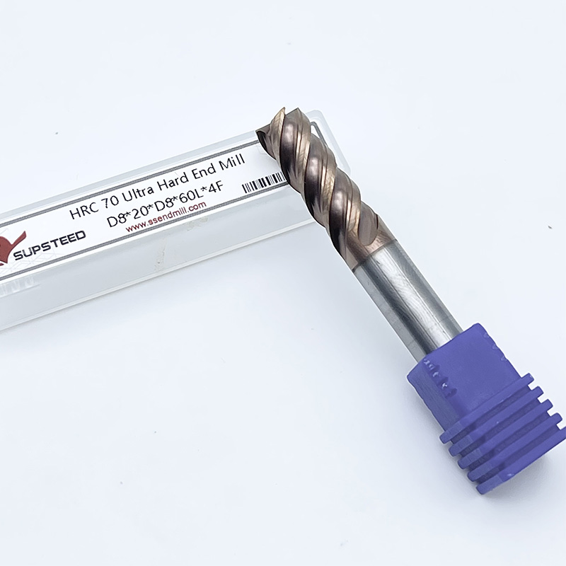
When machine rigidity is limited, the milling tool should be selected more carefully. The goal is to reduce cutting force, improve stability and avoid excessive deflection.
Useful tool features may include:
suitable tool diameter;
shorter flute length when possible;
stronger core design;
suitable helix angle;
variable pitch or variable helix geometry;
appropriate corner radius;
coating matched to material;
carbide grade matched to machining condition;
geometry suitable for roughing or finishing;
proper chip evacuation design.
Carbide milling tools with suitable geometry can help reduce vibration risk, but tool choice must still match the machine. For example, a high-performance end mill designed for aggressive cutting may not perform well if the spindle, holder or workholding cannot support the required cutting force.
The right tool is not always the most aggressive tool. It is the tool that matches the machine, material and machining strategy.
Tool overhang has a strong effect on milling stability. The longer the tool extends from the holder, the easier it is for the tool to bend and vibrate.
Long overhang may be required for:
deep pockets;
tall walls;
mold cavities;
hard-to-reach features;
narrow slots;
complex component geometry.
When deep pockets or extended reach features require longer tool overhang, Long Reach End Mills should be selected carefully to balance reach, rigidity and deflection control.
For long reach machining, buyers should consider:
tool diameter;
flute length;
neck length;
shank strength;
holder grip length;
cutting depth;
radial engagement;
material hardness;
finishing allowance;
vibration tendency.
A long tool should not be used with the same parameters as a short, rigid tool. Cutting depth, feed per tooth and engagement should be adjusted to control deflection and chatter.
Cutting parameters must match rigidity. If the machine, holder and workholding are rigid, the process may support higher material removal. If the setup is weak, the same milling tool may need lower engagement and more conservative cutting conditions.
Important parameters include:
spindle speed;
feed per tooth;
axial depth of cut;
radial depth of cut;
step-over;
toolpath strategy;
coolant or air blast;
entry method;
climb or conventional cutting strategy;
finishing allowance.
When chatter appears, operators may need to reduce radial depth of cut, adjust spindle speed, reduce tool overhang or change toolpath strategy. For roughing, the goal is to remove material efficiently without creating unstable cutting force.
For heavy roughing where cutting force is high, Roughing End Mills can help improve chip removal and reduce cutting load when they are matched with a rigid setup and suitable parameters.
Parameter adjustment should never be random. It should be based on machine condition, tool size, material, holder, workholding and required finish.
| Rigidity Issue | Tool Selection / Process Response |
|---|---|
| Long overhang required | Use shorter flute length, stronger core or suitable long-reach design |
| Chatter appears | Consider variable pitch, suitable helix and reduced radial engagement |
| Weak workholding | Reduce cutting force and improve fixture support |
| Small machine spindle | Use proper tool diameter and conservative depth of cut |
| Hard material machining | Select suitable carbide grade, coating and edge geometry |
| Poor surface finish | Check runout, overhang, feed per tooth and finishing tool choice |
| Edge chipping | Reduce impact load and choose stronger cutting edge geometry |
This table can help buyers review whether the issue should be solved by changing the tool, improving setup rigidity or adjusting cutting parameters.
Before selecting milling tools, buyers should provide more than just workpiece material. Rigidity-related details are also important.
Useful questions include:
What machine type is used?
What spindle condition is expected?
What tool holder type is used?
What is the tool overhang?
Is the workpiece clamped firmly?
Is the part thin-walled or unstable?
What material is being machined?
Is the process roughing or finishing?
What axial depth of cut is planned?
What radial depth of cut is planned?
Is chatter already visible?
Is edge chipping the main problem?
What surface finish is required?
What tool life target is expected?
Is long reach machining required?
These details help the supplier recommend a more suitable carbide end mill, coating, flute design and cutting strategy.
SUPSTEED supports milling tool selection for roughing, finishing, hard milling, micro machining and long-reach applications. When customers face chatter, poor finish, short tool life or edge chipping, the issue may involve both tool selection and machining setup.
SUPSTEED can help review:
workpiece material;
machine rigidity;
spindle condition;
tool holder;
workholding;
tool overhang;
machining depth;
current cutting parameters;
roughing or finishing goal;
surface finish requirement;
tool wear pattern;
edge chipping condition;
required tool diameter;
special reach requirement.
For roughing, finishing, hard milling or long-reach milling, SUPSTEED can help match carbide milling tools with machine rigidity, cutting depth, feed per tooth and material conditions.
Machine rigidity affects milling tool performance by controlling vibration, tool deflection, chip load stability, chatter tendency, surface finish, dimensional accuracy and tool life. A rigid setup allows carbide milling tools to perform closer to their designed cutting capability. A weak setup requires shorter overhang, stronger tool geometry, conservative cutting parameters, better workholding and suitable toolpath strategy.
High-quality milling tools can improve cutting stability, wear resistance and edge performance, but they cannot fully compensate for weak machine rigidity, poor clamping or excessive tool overhang. The best result comes from matching the tool with the full machining system.
Send SUPSTEED your workpiece material, machine type, spindle condition, tool holder, tool overhang, cutting parameters, machining goal and current tool problem to discuss a suitable milling tool solution.
Machine rigidity affects milling tools by controlling vibration, tool deflection, chip load stability, surface finish, dimensional accuracy and tool life.
Low rigidity can cause chatter, vibration, poor surface finish, dimensional error, edge chipping and shorter tool life.
Better milling tools can improve stability and wear resistance, but they cannot fully compensate for weak machine rigidity, poor workholding or excessive overhang.
Longer tool overhang reduces stiffness and increases deflection risk. This can cause chatter, poor accuracy and unstable tool wear.
Chatter creates unstable cutting force, surface marks, noise, edge impact and faster tool wear.
Suitable diameter, shorter flute length, stronger core design, variable pitch, proper helix angle, coating and edge geometry can help improve stability.
Less rigid setups may require reduced radial depth of cut, controlled axial depth, adjusted spindle speed, lower cutting force and shorter tool overhang.
Yes. Weak workholding can allow the workpiece to move under cutting force, causing dimensional error, vibration and tool impact.
Yes. Roughing tools experience high cutting force, so machine rigidity, tool holder strength and workholding stability are important.
Yes. SUPSTEED can review material, machine rigidity, tool holder, overhang, cutting parameters and tool wear problems to recommend suitable carbide milling tools.


