Please Choose Your Language
- All
- Product Name
- Product Keyword
- Product Model
- Product Summary
- Product Description
- Multi Field Search

Views: 0 Author: Site Editor Publish Time: 2026-09-22 Origin: Site

You pull a freshly engraved acrylic panel off the vacuum table. Instead of crisp, frosted lettering, you find melted plastic edges and fuzzy details. These frustrations frequently ruin intricate designs and inflate scrap rates on the shop floor. However, the root cause is rarely the CNC machine itself. More often than not, operators mistakenly rely on standard metal-cutting bits to process nonmetals. They overlook the fact that materials like cast acrylic, MDF, and advanced composites possess vastly different thermal and structural properties compared to steel or aluminum.
To achieve clean cuts without thermal damage, shops must transition to dedicated routing solutions. Specifically, the exact geometry of the cutting tool dictates critical machining factors like chip evacuation, heat reduction, and ultimate detail quality. This engineering guide breaks down the principles behind tool selection. It will help you evaluate the exact angles, flute counts, and carbide grades required to achieve flawless surface finishes on plastics, woods, and composites.
Geometry is Everything: The specific angle of your V groove cutter directly controls the width of the cut and the sharpness of fine details. Narrow angles like 30 to 45 degrees are mandatory for micro-text. Wider angles like 60 to 90 degrees serve as the standard for bold commercial sign-making.
Thermal Management: Nonmetals act as thermal insulators. Single-flute designs provide superior chip clearance to prevent heat buildup and material re-welding.
Tip Flatness Matters: A true point creates razor-sharp lines but breaks easily. A cutter engineered with a micro-flat tip, such as 0.1mm or 0.2mm, significantly increases tool life during aggressive deep passes.
Substrate Specificity: The ideal cutter for acrylic requires a highly polished flute. In contrast, routing highly abrasive MDF demands premium micro-grain solid carbide to resist extreme edge wear.
Looking at the broader manufacturing landscape, recent industry data highlights a massive shift toward high-precision nonmetal fabrication. Driven by the booming architectural signage and electronics sectors, particularly PCB isolation routing, manufacturers face increasingly tighter tolerance mandates. Clients now expect zero-rework surface finishes right off the machine bed.
Consequently, the industry trend is moving rapidly away from generic, multi-purpose router bits. Shops are standardizing on highly specialized, material-specific tool geometries. Facilities that fail to adopt these specialized routing technologies struggle with unacceptable scrap rates. They inevitably fall behind competitors who leverage optimized carbide geometries to guarantee pristine edges at high feed rates.
Standard end mills designed for machining metals are engineered to withstand immense cutting forces. They dissipate heat efficiently through the dense metal chips they shear away. Nonmetals behave entirely differently under a high-speed spindle. When a traditional metal-cutting tool attempts to slice through polycarbonate or hardwood, the heat generated by friction does not transfer into the chip. Instead, it remains trapped at the cutting edge.
This trapped heat leads to immediate localized melting, poor chip clearing, and a ruined surface finish. Materials such as PVC demand a sharp slicing action to prevent stress fractures. Fibrous substrates like natural wood require exceptionally keen edges to sever fibers cleanly without tearing. A standard metal tool typically utilizes a neutral or slightly negative rake angle. This geometry tends to plow clumsily through softer materials rather than shearing them cleanly.
Dedicated routing tools are engineered specifically for high-speed routing rather than high-torque milling. They feature distinct characteristics. You will find sharper cutting edges to slice fibers, highly polished flutes to prevent plastic adhesion, and specialized micro-grain carbide grades. These features maintain a keen edge at high spindle speeds, often exceeding 18,000 to 24,000 RPM.
Before specifying a tool for your next production run, you must understand the anatomical terminology of the cutter. This ensures accurate CAM programming and physical execution.
The most common point of confusion lies in the difference between the included angle and the half angle. The included angle refers to the total angle of the V-shape. In contrast, the half angle is measured from the center axis of the tool to one cutting edge. For instance, a cutter boasting a 60-degree included angle means each cutting side sits 30 degrees off the center axis. Modern CNC software typically requires the included angle to generate accurate V-carving toolpaths.
Beyond the primary angle, the rake and clearance angles determine how the tool engages the substrate. High positive rake angles are essential for soft materials. They create a sharper cutting wedge that slices cleanly through plastics without inducing excessive downward pressure. Too much downward force can easily bow thin materials off the vacuum table. Meanwhile, a proper clearance angle ensures that the heel of the tool does not rub against the freshly cut surface. This is a critical factor in preventing friction-induced burn marks in wood.
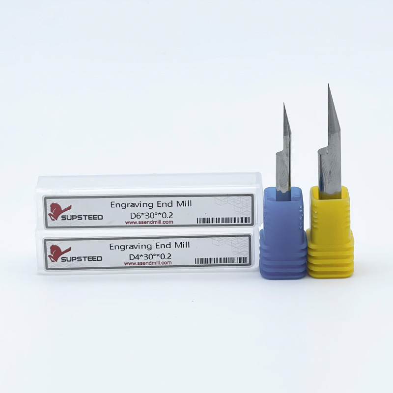
Another vital specification is the tip diameter. Pointed tips provide absolute precision for micro-engraving where lines must taper to a zero-width point. However, this microscopic tip is structurally fragile. It is highly susceptible to snapping under rapid feed rates. To counteract this, industrial manufacturers offer truncated V-bits featuring a micro-flat tip ranging from 0.1mm to 0.3mm. This subtle flat geometry vastly improves durability without sacrificing noticeable detail. It makes the engraving end mill highly reliable for continuous, high-volume production runs.
The chosen angle of the cutter fundamentally limits how deep the tool can plunge before the engraved line becomes too wide for the intended design vector. Matching the angle to the artwork is your first step in optimizing detail quality.
Steep angles, specifically 30-degree and 45-degree cutters, are mandatory for intricate designs and small serif fonts. Because the angle is narrow, the tool can plunge deeper into the material to create a distinct, highly visible groove without excessively widening the cut. This capability allows operators to achieve high-contrast engraving on very small physical footprints.
For general sign-making and medium-sized lettering, the 60-degree cutter represents the industry standard. It offers an optimal balance between depth and width. This provides substantial structural stability to the tool tip while allowing for crisp V-carving on standard fonts.
When routing expansive, shallow areas, 90-degree and 120-degree cutters are the preferred choice. These wide angles clear out broad sections efficiently. They do not require the CNC engraving cutter to plunge dangerously deep into the substrate, which could compromise panel integrity. Furthermore, these tools serve as the standard for edge chamfering and beveling.
Included Angle | Primary Application | Depth vs. Width Characteristic |
|---|---|---|
30° - 45° | Micro-text, PCB isolation, fine line art | Deep plunge yields a very narrow surface width. |
60° | Standard lettering, commercial signage | Balanced ratio. Optimal for medium fonts. |
90° - 120° | Large signs, background clearing, edge chamfering | Shallow plunge yields a very wide surface width. |
Understanding this geometry empowers operators to calculate exact cutting parameters dynamically. Mastering these calculations ensures your CAM simulations perfectly match the physical output on the machine bed.
Moving beyond basic angles, the actual flute configuration dictates how well a tool breathes during aggressive toolpaths. When machining plastics, poor chip evacuation traps material in the cut zone. As friction spikes, these chips melt and re-weld to the workpiece. They can even wrap around the tool itself. This catastrophic phenomenon is known as melt-back. It ruins the surface finish and will eventually snap the solid carbide tip.
To combat this, operators must choose between single-flute and multi-flute designs based on the material's thermal threshold. A single-flute configuration is the ultimate choice for thermo-sensitive plastics. It provides a massive chip pocket. This allows large chips to be curled and ejected instantly. By removing the material rapidly, the heat is carried away with the chip rather than transferring into the tool body.
Conversely, multi-flute tools are highly effective when deployed on harder woods or dense composites. More flutes equate to more cuts per revolution. This yields a remarkably smoother surface finish on fibrous materials. It also allows for much higher feed rates, provided the CNC machine can handle the increased chip load. Operators frequently rely on double-flute nonmetal milling tools when working with rigid hardwoods like oak or maple.
Not all plastics behave uniformly under a high-speed spindle. Cast acrylic machines cleanly and produces distinct, frosty chips when cut correctly. This makes it the premier choice for LED edge-lit signs. Extruded acrylic, however, has a significantly lower melting point. It is notoriously susceptible to gumming up around the cutter. Polycarbonates and PVC present their own unique challenges, requiring highly aggressive chip evacuation to prevent ugly burr formation along the top edge of the cut.
For any plastic application, securing a tool with mirror-finish flutes is a critical specification. A polished flute reduces the coefficient of friction to near zero. When you machine cast acrylic with a polished tool, you want to see crisp chips flying away from the cut zone. If the chips start looking like stringy, melted webs, your tool either lacks the necessary polished flute or has become dull.
When making purchasing decisions regarding plastics, operators should specifically seek out a solid carbide, single-flute plastic engraving tool featuring an O-flute geometry. A high positive rake angle is mandatory here to ensure a burr-free, perfectly frosted engraved finish.
Natural wood and MDF are inherently fibrous. If the cutting edge of the router bit is even slightly dull, the instrument will tear and crush the fibers rather than slicing them. This results in fuzzy, frayed edges that demand labor-intensive post-processing and manual sanding. Maintaining absolute edge sharpness is non-negotiable for these substrates.
The challenge intensifies when dealing with abrasives. MDF is manufactured using dense, abrasive glues and resins. Similarly, advanced composites like carbon fiber or FR4 contain highly abrasive structural strands. These materials act essentially like sandpaper against cutting tools. They rapidly degrade the sharp V-point required for fine detail work.
To combat this severe abrasive wear, buyers must select tools manufactured from premium solid micro-grain carbide. Unlike standard high-speed steel or lower-grade carbides that dull quickly, micro-grain carbide maintains its structural integrity. It retains its edge exponentially longer when subjected to the harsh friction of composite resins. Investing in high-grade carbide directly translates to fewer tool changes and more consistent detail quality across long production batches.
Making an informed purchasing decision requires methodically matching the tool's engineering specifications to the exact demands of your workpiece. Use this practical checklist to ensure you acquire the correct cutter for your specific shop environment:
Identify the Primary Material: Determine if thermal properties dictate a single-flute polished tool for plastics, or if abrasive properties dictate a multi-flute micro-grain carbide tool for composites.
Determine the Smallest Detail Size: Analyze your vector design closely. The smallest gap in the artwork dictates the required included angle. Choose 30 degrees for fine lines and 60 degrees for standard text.
Select the Right Tip: Specify a 0.1mm to 0.2mm micro-flat tip for production runs to prevent tip breakage, reserving true-point cutters strictly for delicate, shallow micro-engraving.
Match the Shank Size: Always match the tool shank size exactly to your CNC collet. Standard industrial sizes include 3.175mm, 4mm, and 6mm. Relying on adapters introduces runout. Wobble will instantly snap a fragile 30-degree V-point and severely degrade detail quality.
Selecting the correct geometry is the foundation that enables the operator to optimize machining parameters. A properly specified tool allows for lower spindle RPMs and higher feed rates. This maximizes chip size, minimizes heat generation, and ultimately drives up production profitability.
Success in nonmetal routing extends far beyond the rigidity of your CNC machine. It is entirely dependent on the geometry of the cutting tool engaging the material. By matching the precise V-groove angle to your design details and prioritizing single-flute, polished geometries for thermo-sensitive plastics, you can eliminate melted edges for good.
Stop compromising your surface finishes with generic metal-cutting bits. Browse our comprehensive catalog of high-precision nonmetal machining tools engineered specifically for your exact material needs. Visit ssendmill.com today to find the exact solid carbide geometries required to optimize your next production run for maximum efficiency and flawless detail.
While physically possible, it is highly discouraged. Metal tools feature different rake angles and smaller chip flutes designed for dense materials. When used on nonmetals, these geometries fail to evacuate chips quickly. This causes plastics to melt from friction and wood to burn or tear. You should always utilize dedicated nonmetal milling tools engineered for the specific thermal and structural properties of your substrate.
For fine, intricate text and micro-details, a 30-degree or 45-degree V-groove cutter is optimal. The steep angle allows the CNC machine to carve deeply enough into the material to create a clean, highly visible line without making the text look excessively wide, overlapping, or muddy at the surface level.
Burrs along the top edge of a cut are primarily caused by heat buildup and dull cutting edges. Ensure you are using a razor-sharp, single-flute plastic engraving tool with polished flutes to reduce friction and prevent plastic adhesion. Additionally, optimize your parameters by lowering your spindle speed and increasing your feed rate. This creates larger chips that effectively carry heat away from the cut zone before it can melt the surrounding edge.
A pointed V-bit tapers to an absolute sharp point, offering maximum precision for microscopic details. However, the tip is highly fragile and prone to snapping under heavy feed rates. A flat-tip cutter features a microscopic flat area at the very tip, typically between 0.1mm and 0.3mm. This subtle modification vastly improves tool durability and lifespan while still delivering excellent detail quality for the vast majority of industrial applications.
The goal is to maximize chip size to carry heat away from the tool. Start with a moderate spindle speed around 16,000 to 18,000 RPM and push the feed rate as high as your CNC machine and material hold-down system will allow without chattering. If the plastic is melting, your spindle speed is too high or your feed rate is too low. If the tool is snapping, decrease the feed rate or reduce the plunge depth per pass.
Tool breakage in dense, abrasive materials usually stems from two main issues: excessive runout or chip packing. If your collet is dirty or worn, the tool will wobble and snap the fragile tip. Alternatively, if you are plunging too deep in a single pass without proper chip evacuation, sawdust packs into the flute. This drastically increases cutting pressure until the carbide shears. Always clear chips efficiently and use a micro-flat tip for added structural strength.