- All
- Product Name
- Product Keyword
- Product Model
- Product Summary
- Product Description
- Multi Field Search

Views: 0 Author: Site Editor Publish Time: 2026-08-26 Origin: Site

Treating wood as a uniform material during CNC routing guarantees suboptimal surface finishes, excessive tool wear, and scrapped parts. The operational reality of machining timber and engineered panels is that each substrate presents distinct mechanical challenges. Shop floors frequently face the time-consuming burden of tear-out in veneered plywood, rapid edge dulling from abrasive MDF binders, and friction-induced burning in dense hardwoods. Relying on a single general-purpose router bit across all these materials leads directly to failed cuts and ruined stock.
Selecting the correct cnc end mills for wood requires matching flute geometry, cutting direction, and carbide grade to the specific structural properties of the target material, whether it is natural timber or an engineered composite. Understanding how a tool interacts with cross-laminated veneers, homogeneous resin-bound cores, or directional grain structures dictates the success of the machining operation.
A successful CNC routing operation in wood is defined by strict physical outcomes. The primary goal is achieving zero tear-out on both the entry and exit surfaces of the cut. Burn marks must be entirely absent, indicating that the tool sheared the material rather than rubbing against it. Dimensional accuracy must remain within the required tolerances, free from the effects of tool deflection or spindle runout. Finally, maximizing tool life ensures the operation remains efficient, reducing the frequency of tool changes and machine downtime. Achieving these criteria requires a precise understanding of cutting mechanics and material behavior.
Operators measure this success directly on the machine bed. You use digital calipers to verify that a 0.500-inch slot is exactly 0.500 inches wide. If the slot measures 0.510 inches, you are likely dealing with tool deflection or spindle runout. Visual inspection confirms the absence of fuzz or splintering on the top edge of a melamine sheet. When the physical outcomes fail to meet these standards, the first variable to investigate is always the cutting tool.
Natural wood and engineered composites behave entirely differently under the shear forces of a rotating cutter. Natural timber features a directional grain structure. Cutting with the grain, against the grain, or across the end grain alters the resistance the tool encounters. This unpredictability increases the risk of splintering, especially when the cutter exits the material. Knots and changing grain directions can grab the tool, causing sudden spikes in cutting force.
Engineered composites like Medium-Density Fiberboard (MDF) or particleboard possess an omnidirectional, homogeneous core. They lack unpredictable grain patterns. However, they are saturated with abrasive glues and resins. This shifts the primary machining challenge from managing tear-out to combating rapid edge degradation and managing fine, abrasive dust. You do not have to worry about grain direction in MDF, but you must plan for severe tool wear.
The fundamental mechanism of milling dictates that the tool must shear material to create a chip. In woodworking, chips serve a secondary function: they carry heat away from the cutting zone. If chips are not evacuated efficiently, they remain in the toolpath. The cutter then recuts the same material. This friction generates immense heat.
In dense hardwoods, trapped heat quickly causes burn marks on the edge of the workpiece. If the temperature exceeds the thermal threshold of the carbide, the tool will anneal. It loses its hardness and dulls instantly. Effective chip evacuation is the absolute prerequisite for clean cuts and sustained tool longevity. If you are making fine dust instead of distinct chips when cutting solid wood, your tool is absorbing the heat instead of shedding it.
Cross-laminated materials like plywood and brittle-surfaced boards like melamine are highly susceptible to lifting and splintering. The top and bottom veneers or plastic shells lack the structural support to withstand the upward or downward pulling forces of standard router bits. When an upcut bit exits the top surface, it pulls the veneer away from the core, causing severe tear-out. A downcut bit pushes the bottom veneer away from the core upon exiting the underside.
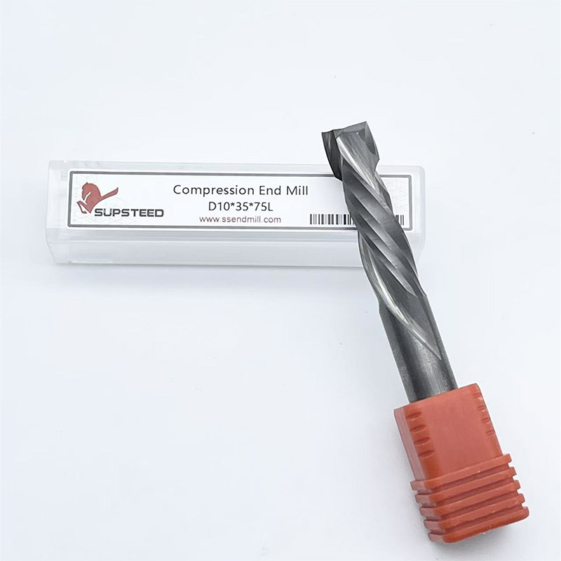
Compression end mills solve this exact problem. These specialized tools combine upcut and downcut geometries on the same flute. The lower portion of the bit features an upcut geometry, pulling the bottom edge upward. The upper portion features a downcut geometry, pushing the top edge downward. This simultaneous shearing action compresses the material toward the center of the core, leaving pristine, splinter-free edges on both sides of double-sided laminates.
Implementing compression bits requires specific toolpath strategies. The first pass must plunge deep enough so that the downcut portion of the flute engages the top surface of the material. If the initial pass is too shallow, only the upcut portion engages, which will immediately splinter the top veneer. Follow these steps to set up a compression toolpath:
Medium-Density Fiberboard presents a unique tooling challenge due to its material composition. The dense, glue-heavy nature of MDF acts as a continuous abrasive against the cutting edge. Standard high-speed steel will lose its edge within minutes of routing MDF. The urea-formaldehyde resins require tooling capable of withstanding constant abrasion without losing the micro-geometry of the cutting edge.
For homogeneous materials like MDF, straight flute or downcut solid carbide end mills are optimal. Because MDF lacks a directional grain, the risk of splintering is low, but maintaining a crisp top edge is expected. A downcut bit shears the surface fibers cleanly downward. Since MDF produces fine, powdery dust rather than distinct chips, the aggressive chip-clearing capabilities of an upcut bit are less critical.
Dust packing in the cut channel causes friction. You need adequate dust extraction systems. A standard shop vacuum is rarely sufficient for production MDF routing. You need a high-velocity dust collector pulling adequate CFM directly from the spindle shroud to evacuate the heavy dust before it packs into the kerf and overheats the tool.
Dense hardwoods such as oak, maple, and walnut generate significant friction during the cutting process. If the tool rubs rather than shears, the wood will burn rapidly. Burning is typically caused by incorrect feed rates (moving too slowly) or dull cutting edges. To machine hardwoods effectively, operators specify 2-flute upcut solid carbide end mills for deep profiling. The upcut geometry aggressively pulls chips out of the cut, removing heat and preventing the tool from binding in the dense grain.
Softwoods like pine or cedar introduce a different variable: resin and pitch. The primary risk when routing softwoods is the resin melting from friction and adhering to the cutter. Once resin packs into the flutes, the tool can no longer clear chips, leading to immediate overheating and tool failure. Machining softwoods requires wood CNC end mills with highly polished flutes. Single-flute (O-flute) designs provide massive gullets for unobstructed chip ejection and prevent gummy buildup.
When interacting with unpredictable natural grain patterns, the choice between climb milling and conventional milling strategies becomes critical. Climb milling, where the cutter rotates in the direction of the feed, generally leaves a superior surface finish in solid wood by shearing the grain cleanly. It requires a rigid machine setup, as the tool tends to pull itself into the material. Conventional milling is safer on lighter machines but can cause tear-out when cutting against the grain.
Material to Tool Geometry Matching Guide
| Material Type | Primary Challenge | Recommended Flute Geometry | Preferred Flute Count |
|---|---|---|---|
| Veneered Plywood | Top and bottom edge tear-out | Compression | 2-Flute |
| Melamine / Laminate | Brittle surface chipping | Compression | 2-Flute |
| MDF / Particleboard | Abrasive wear, dust packing | Straight or Downcut | 2-Flute |
| Dense Hardwood | Friction burning, heat buildup | Upcut | 2-Flute |
| Softwood / Resinous | Pitch buildup, chip packing | Upcut (Polished O-Flute) | 1-Flute |
The direction of the flute determines how the tool applies force to the material and where the chips are directed. Upcut bits feature a right-hand spiral that pulls chips upward and away from the cutting zone. This facilitates fast chip removal and excellent heat dissipation, making it ideal for deep slots and blind pockets. The upward pulling action leaves a rough top edge and requires strong vacuum hold-down or mechanical clamping to prevent the workpiece from lifting off the spoilboard.
Downcut bits utilize a left-hand spiral to push chips downward. This action presses the material against the CNC bed, aiding in workholding, and shears the top surface cleanly downward, preventing tear-out. The drawback is that chips are trapped in the cut channel. This increases heat buildup significantly, making downcut bits suitable only for shallow pockets, thin materials, or first-pass scoring cuts on delicate top veneers.
Straight flute bits exert neutral cutting forces. They neither pull up nor push down. They provide acceptable performance for general-purpose routing in MDF or plastics. They lack the aggressive shearing angle required for clean cuts in natural hardwoods and do not evacuate chips as efficiently as spiraled geometries.
The number of flutes on a cutter directly influences the feed rate, surface finish, and chip clearance capacity. Single flute bits, commonly referred to as O-flutes, offer the maximum possible chip clearance. While heavily utilized for plastics and non-ferrous metals, they are highly effective for very soft, resinous woods. The large open gullet prevents resin from packing, making them ideal for high-speed roughing on lighter machines that cannot sustain the feed rates required for multi-flute tools.
Two-flute end mills represent the industry standard for wood routing. They offer the optimal balance of chip clearance, structural rigidity, feed rate capability, and surface finish. A two-flute tool allows for a stable cutting action while leaving enough open space in the flute valley to evacuate wood chips efficiently.
Three-flute bits and above are strictly reserved for industrial machines with high-horsepower spindles. Adding more flutes reduces the size of the chip gullet. To maintain the proper chip load and prevent the tool from rubbing and burning the wood, the machine must push the tool through the material at significantly higher feed rates. Desktop or hobbyist machines lack the rigidity and acceleration to utilize three-flute bits effectively in wood.
Standard routing operations frequently require the tool to plunge directly into the face of the material. To execute a vertical plunge without pre-drilled holes, the end mill must be center-cutting. Center-cutting tools have cutting edges that extend entirely to the center of the tool's tip, allowing them to drill straight down. Non-center-cutting tools leave a small dead zone in the middle, which will crash into the material if plunged vertically.
Even with center-cutting bits, plunging straight down into dense hardwoods causes rapid wear on the tool tip and increases the risk of bottom-edge burning. Operators should utilize ramping toolpaths. Ramping enters the material at an angle, simultaneously moving in the X, Y, and Z axes. This distributes the cutting force along the side of the flute rather than concentrating it solely on the tip, extending tool life and ensuring a cleaner entry.
Beyond standard square end mills, specific profiles are required for complete CNC woodworking operations. Spoilboard or table-surfacing cutters are massive, flat-bottomed tools essential for tramming the CNC bed. Surfacing the sacrificial spoilboard ensures perfectly flat stock mounting, which is critical for accurate depth-of-cut across the entire work area.
Ball nose bits feature a fully radiused tip. They are mandatory for 3D carving, topographical relief work, and machining complex contours in solid wood. The rounded tip allows for smooth stepovers, leaving a contoured surface rather than the stair-step effect caused by flat end mills.
V-Bits are utilized for engraving, chamfering, sign-making, and sharp corner detailing. By varying the Z-depth of a V-bit, the CNC can create variable-width lines, a technique heavily used in V-carving typography and decorative panels.
The material from which the router bit is manufactured dictates its operational lifespan and performance threshold. High-Speed Steel (HSS) is effectively obsolete for modern CNC wood routing. The abrasive nature of engineered panels and the high spindle speeds of CNC routers cause HSS to dull almost immediately. Solid carbide is the mandatory baseline for performance. Micro-grain solid carbide maintains a razor-sharp edge through thousands of linear feet of cutting, withstanding the heat and abrasion that destroy lesser alloys.
For high-volume production environments processing continuous sheets of MDF or melamine, insert tooling offers a distinct advantage. Insert router bits utilize a steel tool body with replaceable solid carbide knives screwed into the flutes. When the edge dulls, the operator simply rotates or replaces the small carbide insert rather than discarding the entire tool. This maintains exact tool diameter and length, reducing setup time and recalibration at the machine controller.
Specialized coatings, such as Titanium Nitride (TiN) or Diamond-Like Carbon (DLC), are common in metalworking but require careful evaluation for wood applications. Wood does not generate the same chemical wear as steel, and the primary failure mode is abrasion or resin buildup. Coatings can reduce friction and extend edge life slightly in abrasive MDF, but many operators find that uncoated micro-grain solid carbide performs exceptionally well when feed rates are optimized.
Tool selection cannot be divorced from the physical capabilities of the CNC machine executing the cut. A compact 3-axis desktop machine utilizing a 1.5kW spindle and 1/4-inch shank tooling requires entirely different feed rate strategies compared to a gantry-style industrial router equipped with a 12.5kW spindle and 1/2-inch tool holders. Heavy industrial machines possess the mass and rigidity to push large-diameter tools through dense hardwoods at high speeds without vibration. Desktop machines lack this rigidity. Forcing an aggressive cut will result in skipped steps, severe chatter, and broken tools. Operators of lighter machines must utilize smaller diameter bits, shallower depths of cut, and highly polished single or double-flute geometries to reduce cutting forces.
Calculating and maintaining the optimal chip load is the most critical mathematical requirement in CNC routing. Chip load represents the physical thickness of the wood chip removed by a single cutting edge during one revolution. The formula is: Feed Rate = RPM × Number of Flutes × Chip Load. If the chip load is too low, the tool rubs, generates heat, and burns the wood. If the chip load is too high, the cutting forces exceed the tool's strength, leading to deflection and breakage. Follow this process to dial in feeds and speeds on a new material:
Tool deflection is a severe implementation risk when using long, small-diameter bits in dense materials. Deflection occurs when the lateral cutting forces cause the end mill to bend slightly during the cut. This bending leads to dimensional inaccuracy, poor surface finish, and catastrophic tool breakage. To mitigate deflection, operators must use the shortest possible tool length that allows for the required depth of cut, maximize the shank diameter, and ensure the collet grips the tool securely.
A: While metalworking end mills can physically cut wood, they are highly inefficient. Metal cutting tools feature shallow chip gullets designed for small metal chips, which quickly pack with wood fibers and resin. This leads to friction, burning, and tool failure. Always use dedicated wood end mills with deep flutes for proper chip evacuation.
A: Burning is caused by friction when the tool rubs against the wood instead of shearing it. This typically happens when the feed rate is too slow, the spindle RPM is too high, or the cutting edge is dull. Increase your feed rate or lower your RPM to achieve a proper chip load.
A: An upcut bit pulls chips and material upward, which clears heat quickly but causes tear-out on the top surface of veneered materials. A compression bit combines upcut and downcut flutes to push the top and bottom surfaces toward the center of the material, leaving clean edges on both sides of plywood or melamine.
A: Tool life depends heavily on feed rates, chip load, and the specific resin content of the MDF. Under optimized industrial conditions, a high-quality solid carbide bit can cut several thousand linear feet before edge degradation affects cut quality. Using insert tooling is recommended for continuous, high-volume MDF production.
A: Use a double flute end mill as your standard tool for hardwoods and sheet goods, as it balances feed speed and surface finish. Use a single flute (O-flute) when cutting soft, resinous woods like pine, or if you are using a low-rigidity desktop machine that requires lower cutting forces.
A: Top-edge splintering occurs when using an upcut bit that pulls the delicate surface veneer away from the core. To fix this, switch to a downcut bit for shallow cuts, or use a compression bit for full-depth profile cuts to shear the top veneer cleanly downward.
A: A dedicated spoilboard surfacing cutter, also known as a fly cutter or bottom-cleaning bit, is required. These tools feature a large cutting diameter and flat bottom geometry to quickly and accurately tram the MDF bed, ensuring a perfectly level work surface.