Please Choose Your Language
- All
- Product Name
- Product Keyword
- Product Model
- Product Summary
- Product Description
- Multi Field Search

Views: 0 Author: Site Editor Publish Time: 2026-07-30 Origin: Site

Machining aerospace components involves incredibly high stakes on the shop floor. Scrapped parts due to tool failure, poor surface finish, or unexpected stress warpage cost thousands of dollars per unit and disrupt entire production schedules. Machinists face severe difficulties when cutting Heat-Resistant Superalloys (HRSAs), titanium alloys, and hybrid Additive Manufactured (AM) near-net-shape components. Standard commercial tooling suffers from rapid edge wear and catastrophic failure under these conditions. Basic cutters simply cannot maintain tight aerospace tolerances when subjected to extreme thermal loads and abrasive material properties.
Evaluating specific tool geometries, carbide substrates, and advanced coatings is absolutely necessary for shop survival. You must select the correct aerospace end mill for high-efficiency milling (HEM) and traditional toolpaths. Proper selection prevents premature failure, controls heat generation, and ensures dimensional accuracy across complex airframe and engine components. We will break down the exact parameters required to optimize metal removal rates in difficult aerospace materials.
Material-Specific Geometry is Non-Negotiable: Successful HRSA machining requires variable helix and variable pitch designs to disrupt harmonics and prevent chatter.
Coating Dictates Thermal Management: Advanced PVD coatings (like AlTiN or silicon-doped nanocomposites) are critical for protecting the carbide substrate from the extreme heat generated by titanium and Inconel.
Edge Prep Determines Tool Life: Micro-geometry, T-lands, and edge honing prevent premature chipping in work-hardening materials.
Additive Post-Processing Demands Adaptability: Machining 3D-printed or sintered titanium/Inconel requires specialized parameter adjustments to handle inconsistent skin hardness and abrasive scale.
Tool Holding Impacts Performance: Even the highest-quality end mill will fail without rigid, high-concentricity tool holding (e.g., shrink fit or hydraulic chucks).
Titanium and Inconel possess notoriously low thermal conductivity. These materials transfer heat directly into the cutting tool rather than the chip. This thermal concentration causes rapid substrate degradation and plastic deformation of the cutting edge. You must utilize specific tool parameters to prevent thermal breakdown during heavy roughing passes. Proper geometries allow the tool to evacuate heat efficiently through optimized chip formation. When heat stays in the cut zone, the carbide binder breaks down, leading to immediate edge failure. Managing this heat requires a combination of the right coating, proper coolant application, and precise feed rates to ensure the chip carries away as much thermal energy as possible.
On the machine, operators often see tools glow red when parameters are incorrect. This indicates that the thermal barrier of the coating has failed. Once the coating breaches, the raw carbide absorbs the heat, expanding and micro-chipping. We combat this by adjusting the radial depth of cut. Lower radial engagement reduces the time the cutting edge spends in the material per revolution. This allows the tool to cool slightly during the non-cutting portion of the rotation. It is a delicate balance between maintaining high metal removal rates and keeping the tool temperature within safe operating limits.
Localized work hardening poses a massive risk during HRSA machining. Cutting forces alter the material grain structure ahead of the tool. If you allow a tool to rub rather than cut, the surface hardens instantly. The next pass will destroy the cutting edge as it tries to penetrate this hardened layer. Material welding to the cutting edge creates a Built-Up Edge (BUE). This phenomenon rips microscopic carbide particles from the tool upon detachment. Establishing strict baseline requirements for edge preparation prevents this rapid degradation. A sharp but properly honed edge shears the material cleanly without excessive rubbing.
BUE is particularly troublesome in titanium applications. The material has a high chemical affinity for the cobalt binder used in carbide tools. Under high heat and pressure, the titanium literally welds itself to the flute face. When the chip finally breaks away, it takes a piece of the tool with it. We prevent this by using highly polished flutes and specific coatings that resist chemical bonding. Maintaining a constant chip load is also vital. If the feed rate drops, the tool rubs, heat spikes, and BUE forms rapidly. Modern CAM software helps maintain this constant chip load even in tight corners.
Milling 3D-printed or sintered near-net-shape aerospace parts introduces unique complexities to the shop floor. Inconsistent material density and skin-depth hardness variations destroy standard cutting edges. Abrasive surface scale acts like sandpaper on the tool substrate. Internal residual stresses frequently cause part warpage during metal removal. You must adapt machining parameters to handle these unpredictable material states. The outer crust of an AM part often requires a sacrificial roughing tool or a highly specialized cutter designed specifically to break through the abrasive layer without fracturing.
Once you penetrate the outer scale, the internal material properties can still vary. Porosity and un-melted powder pockets cause interrupted cutting conditions on a micro-scale. This constant shock loading requires a tough carbide substrate rather than a purely hard one. We often reduce cutting speeds by 20 to 30 percent when machining AM parts compared to wrought billets of the same alloy. Fixturing also becomes a major challenge. AM parts often have complex, organic shapes that are difficult to hold rigidly. Any vibration in the setup will transfer directly to the tool, accelerating wear and causing poor surface finishes.
A successful tooling choice is measured by Cost Per Part (CPP) and predictable tool life. Adherence to strict surface finish requirements matters far more than initial tool purchase price. Predictability allows for lights-out manufacturing and reduces the risk of scrapping high-value aerospace components. If a cheap tool fails unpredictably halfway through a finishing pass on a $50,000 titanium bulkhead, the savings are instantly negated. We evaluate tools based on how many linear inches they can cut reliably before the wear land reaches a specific threshold.
Shop managers must track tool life data meticulously. We use spindle load monitoring to detect wear before it causes catastrophic failure. A gradual increase in spindle load indicates normal flank wear. A sudden spike indicates chipping or BUE formation. By establishing a baseline for each tool and material combination, we can swap tools proactively. This data-driven approach ensures consistent part quality and maximizes machine uptime. Success is a stable, repeatable process that operators can trust shift after shift.
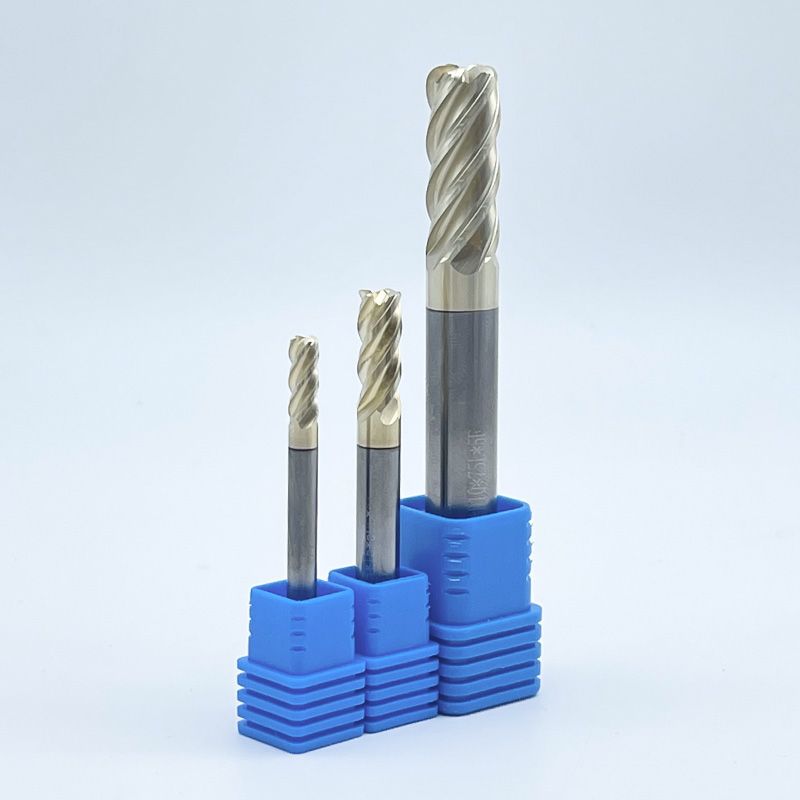
Evaluate 4-flute versus 5+ flute designs based on your specific operation. Slotting requires fewer flutes for maximum chip clearance. Dynamic milling operations benefit from higher flute counts to maximize feed rates. Titanium machining demands larger gullets for proper chip evacuation. Crowded gullets lead to chip recutting and immediate tool failure. When you recut a titanium chip, you are cutting work-hardened material. This destroys the cutting edge instantly. We typically use 4-flute or 5-flute tools for heavy roughing in titanium to ensure adequate space for the chips to escape the cut zone.
For finishing operations or high-efficiency milling (HEM) with low radial engagement, we switch to 7-flute or 9-flute tools. The low radial depth produces a very thin chip, which requires less gullet space. The higher flute count allows for significantly higher table feed rates while maintaining the same chip load per tooth. This drastically reduces cycle times on complex aerospace profiles. However, you must ensure your machine control can process the code fast enough to maintain the programmed feed rate. If the machine stutters, the tool will rub and fail.
Harmonic disruption is critical for eliminating chatter on thin-walled parts. Variable helix and variable pitch designs alter the timing of cutting edge impacts. This physical disruption prevents resonant frequencies from building up. Chatter elimination remains a critical evaluation dimension for machining thin-walled aerospace components. When a standard end mill cuts, each flute hits the material at the exact same interval. This creates a rhythmic vibration. If this vibration matches the natural frequency of the part or the machine, chatter occurs. Chatter leaves a terrible surface finish and destroys the tool.
By varying the pitch (the spacing between the flutes) and the helix angle (the twist of the flutes), we break up this rhythm. One flute might hit at 88 degrees, the next at 92 degrees. This constant variation prevents the vibration from amplifying. This geometry is absolutely mandatory when machining deep pockets or thin ribs in aerospace structural components. It allows us to run higher spindle speeds and deeper axial cuts without inducing chatter. The difference in performance between a standard tool and a variable geometry tool in these applications is night and day.
Tool designers balance core thickness against flute depth. A thick core reduces deflection during heavy roughing cuts. However, a thicker core reduces available space for chip clearance. You must match the core diameter to the specific radial engagement of your programmed toolpath. For traditional slotting, you need a smaller core to provide large gullets. For HEM toolpaths where radial engagement is kept below 15 percent, you want the thickest core possible. A thick core provides the rigidity needed to utilize the entire flute length without the tool bending away from the cut.
Tool deflection causes dimensional inaccuracies and tapered walls. In aerospace, where tolerances are often held to tenths of a thousandth of an inch, deflection is unacceptable. We calculate the theoretical deflection based on the tool's core diameter, stick-out length, and cutting forces. If the deflection exceeds our tolerance, we must reduce the feed rate, take a lighter cut, or select a tool with a larger core. Using tools with a tapered core—where the core diameter increases toward the shank—provides excellent rigidity while maintaining adequate chip clearance at the tip.
T-lands, hones, and micro-geometries reinforce the cutting edge against severe shear forces. Raw, sharp carbide chips easily when cutting HRSAs. Controlled edge preparation distributes cutting forces over a larger area. This micro-geometry prevents premature chipping in aggressive aerospace applications. A dead-sharp edge is actually quite weak. When it hits a hard spot in Inconel or titanium, it fractures. By applying a microscopic hone or a small chamfer (T-land) to the edge, we direct the cutting forces into the strongest part of the carbide substrate.
The size of the hone must be matched to the chip load. If the hone is larger than the programmed chip load, the tool will rub instead of cut. This causes massive heat generation and work hardening. Tool manufacturers use specialized brushing and dragging processes to apply these edge preparations with incredible precision. When evaluating tools, we always inspect the edge prep under a microscope. A consistent, uniform hone is a sign of a high-quality aerospace tool. Inconsistent edge prep leads to unpredictable tool life.
Radial engagement and the arc of contact dictate tool survival. Roll-in entry techniques mitigate initial entry shock. Proper tool orientation manages chip thinning effects during high-speed machining. Programming smooth transitions prevents sudden spikes in spindle load. Never plunge an end mill straight down into titanium or Inconel. This traps chips under the tool and destroys the center cutting edges. Always use a helical ramp or a pre-drilled start hole. The ramp angle should be kept shallow, typically between 1 and 3 degrees, to minimize axial cutting forces.
When entering the side of a part, use an arc-in move rather than a straight line. This gradually increases the radial engagement, allowing the tool to absorb the cutting forces smoothly. We also utilize radial chip thinning calculations. When the radial depth of cut is less than 50 percent of the tool diameter, the actual chip thickness is less than the programmed feed per tooth. You must increase the feed rate to achieve the desired chip thickness. Failure to account for chip thinning results in rubbing, heat generation, and rapid tool wear.
| Parameter | Standard End Mill | Aerospace End Mill |
|---|---|---|
| Helix Angle | Uniform 30° or 45° | Variable (e.g., 35°/38°) |
| Pitch | Equal spacing | Unequal spacing |
| Core Diameter | Standard (approx. 50%) | Thick core (up to 70%) |
| Edge Prep | Sharp / Unhoned | Engineered hone / T-land |
| Carbide Grain | Micro-grain | Ultra-fine sub-micron |
Machining titanium requires specific optimal parameters. You need sharp cutting edges combined with high positive rake angles. Specific coatings must resist chemical reactivity with titanium at elevated temperatures. A dedicated titanium aerospace end mill prevents material adhesion and maintains edge integrity. The high positive rake angle reduces cutting forces and shears the material cleanly, minimizing heat generation. We look for tools with polished flutes to help evacuate the sticky titanium chips quickly before they can weld to the tool face.
Address parameter adjustments when machining sintered titanium surface crusts versus wrought alloys. Additive materials require slower initial entry feeds to penetrate the abrasive skin. High-torque, low-RPM roughing demands different geometries than high-speed finishing operations. For roughing wrought titanium, we use tools with a slightly heavier edge hone to withstand the high torque. For finishing, we switch to tools with a sharper edge and a higher flute count to achieve the required surface finish. Coolant application is critical; high-pressure coolant directed precisely at the cutting zone is mandatory to flush chips and control heat.
Nickel-based alloys generate extreme abrasive wear and high cutting forces. Optimal parameters require ultra-fine-grain carbide substrates. Heavy edge preparation withstands the brutal shear forces. An Inconel aerospace milling cutter must maintain its structural integrity under massive thermal loads. Inconel retains its strength at very high temperatures, which means the cutting forces do not drop as the material heats up. This places immense mechanical stress on the tool. We use tools with a very thick core and a specialized T-land edge preparation to prevent the cutting edge from crumbling under pressure.
Breaking the outer scale of cast or 3D-printed parts requires aggressive parameters. The cutter must break through the highly abrasive, hard outer crust quickly. Shift toward high-feed milling strategies to direct cutting forces axially. This protects the machine spindle and extends tool life. High-feed mills use a very shallow lead angle, which thins the chip dramatically and directs the cutting forces up into the spindle rather than radially against the tool holder. This allows for extremely high feed rates while maintaining a manageable chip load, making it the most efficient way to rough Inconel components.
5-axis simultaneous machining of turbine blades requires robust center-cutting capabilities. Core strength is vital for complex aerodynamic surfaces. An aerospace ball nose end mill must withstand varied engagement angles without deflecting. When profiling a turbine blade, the tool is constantly changing its angle of attack. The cutting forces shift from the side of the ball to the tip and back again. The tool must have a strong core that extends all the way to the tip to prevent deflection and vibration during these transitions.
Tilting the tool axis prevents the zero-SFM dead spot at the tip. Precise orientation minimizes center wear and maximizes surface finish. Maintaining constant surface speed at the tip remains a significant challenge. Specialized tool geometry mitigates this center wear during complex profiling. At the exact center of a ball nose end mill, the rotational speed is zero. If you cut with the dead center, you are dragging the tool, not cutting. We program 5-axis toolpaths to keep the tool tilted at a 10 to 15-degree angle relative to the surface. This ensures we are always cutting with the effective diameter of the ball, maintaining proper surface footage and extending tool life.
Sharp corners act as dangerous stress risers in aerospace parts. Corner radius end mills distribute cutting forces evenly. This geometry extends tool life and meets strict structural part requirements. An aerospace corner radius cutter is essential for pocketing operations. A sharp square corner on an end mill is the weakest point of the tool. It is the first place to chip when machining tough materials. By adding a radius, we strengthen the corner significantly. This allows us to push the tool harder and achieve higher metal removal rates without fear of catastrophic corner failure.
Corner radius geometry reduces vertical deflection in deep pocketing. This is crucial for thin-walled structural airframe components like bulkheads and ribs. Evaluate radius tolerances carefully to ensure perfect blend accuracy across intersecting toolpaths. Aerospace blueprints dictate specific fillet radii for all internal pockets to prevent fatigue cracking in the final part. The corner radius on the tool must match these requirements exactly. We use optical comparators to verify the radius tolerance on our tools before they ever touch a part. A mismatched radius will cause a step in the blend, resulting in a scrapped part.
Evaluate sub-micron and ultra-fine grain carbide substrates carefully. You must frame the trade-off between hardness and toughness. Hardness provides wear resistance against abrasive materials. Toughness provides shock resistance during interrupted cuts. Aerospace applications usually demand a balanced ultra-fine grain structure. The grain size of the tungsten carbide powder dictates the final properties of the tool. Smaller grains allow for a sharper cutting edge and higher hardness. However, if the grains are too small, the tool becomes brittle. We select substrates with a grain size between 0.2 and 0.5 microns for machining titanium and Inconel.
The cobalt binder content also plays a major role. More cobalt increases toughness but reduces hardness. For roughing operations with heavy interrupted cuts, we use a substrate with a slightly higher cobalt content (around 10 to 12 percent) to absorb the shock. For finishing operations where wear resistance is paramount, we use a lower cobalt content (around 6 to 8 percent). Matching the substrate to the specific operation is just as important as selecting the right geometry.
Compare AlTiN, TiAlN, and newer silicon-doped nanostructured coatings. Evaluate their oxidation temperatures and friction coefficients. Silicon-doped coatings offer superior resistance to chemical dissolution in titanium. These advanced PVD coatings act as a thermal barrier, protecting the vulnerable carbide substrate. AlTiN (Aluminum Titanium Nitride) is the industry standard for machining HRSAs. It forms a protective aluminum oxide layer when exposed to high heat, which shields the tool. However, for extreme applications, we are moving toward nanocomposite coatings.
These nanocomposite coatings incorporate silicon to create a structure that is incredibly hard and highly resistant to heat. They have a lower coefficient of friction than standard AlTiN, which helps chips slide out of the gullet faster, reducing heat buildup. The coating thickness is also critical. Too thick, and the cutting edge becomes dull. Too thin, and the thermal barrier fails prematurely. We rely on tool manufacturers who use advanced PVD (Physical Vapor Deposition) processes to apply these coatings with precise thickness control.
Analyze the necessity of through-tool coolant versus external high-pressure coolant. High-pressure delivery prevents thermal shock and aids chip evacuation in deep pockets. Proper coolant application prevents chips from welding to the cutting edge during aggressive HRSA roughing. Flood coolant is often insufficient for aerospace machining. The vapor barrier created by the intense heat at the cutting edge prevents low-pressure coolant from actually reaching the cut zone. We use high-pressure coolant systems (1000 PSI or higher) to blast through this vapor barrier.
Through-tool coolant is highly recommended for drilling and deep pocket milling. It delivers the coolant exactly where it is needed, flushing chips up and out of the hole. However, for solid end mills, external high-pressure nozzles directed precisely at the tool-workpiece interface are often more effective. You must ensure the nozzles are aimed correctly. If the coolant stream misses the cut zone by even a fraction of an inch, the tool will burn up instantly. Proper coolant management is a critical component of the overall machining strategy.
Never use standard collet chucks for high-performance aerospace milling. We strongly recommend shrink-fit or high-precision milling chucks. Runout must be kept below 0.0002 inches. Excessive runout causes uneven chip loads, leading to immediate and premature tool failure. If a 4-flute tool has 0.001 inches of runout, one flute is taking a massive chip while the opposite flute is barely cutting. This uneven loading destroys the tool rapidly and leaves a terrible surface finish.
Shrink-fit holders provide the best concentricity and gripping force. The holder is heated to expand the bore, the tool is inserted, and as it cools, it grips the tool shank with immense pressure. This eliminates the micro-vibrations associated with collet chucks. Hydraulic chucks are also an excellent option, providing great runout characteristics and superior vibration damping. Investing in high-quality tool holding is mandatory; putting a premium aerospace end mill in a cheap collet chuck is a guaranteed way to waste money.
High-performance aerospace end mills require modern CAM strategies. Trochoidal milling and High-Efficiency Milling maintain a constant chip load. Proper toolpath orientation prevents part warpage in thin-walled sections. Software simulation is mandatory before executing cuts on expensive aerospace alloys. Traditional offset roughing toolpaths create spikes in tool engagement when driving into corners. These spikes cause tool deflection, chatter, and breakage. HEM toolpaths use dynamic circular motions to keep the engagement angle constant.
When machining thin walls, we use a strategy called "waterlining" or alternating step-downs. We machine both sides of the wall simultaneously in small axial increments. This balances the cutting forces and prevents the wall from pushing away from the tool. If you machine one side of a thin wall completely before machining the other, the residual stresses in the material will cause the wall to warp. CAM software allows us to program these complex strategies efficiently, ensuring the part remains dimensionally stable throughout the machining process.
Implement spindle load monitoring and tool life tracking systems. Catch tool wear before catastrophic failure damages an expensive workpiece. Predictive monitoring allows operators to swap tools based on actual wear data rather than guesswork. Modern CNC machines can monitor the electrical current drawn by the spindle motor. As the tool wears, it requires more torque to cut the material, which increases the current draw. We set specific load limits in the machine control.
If the spindle load exceeds the limit, the machine automatically pauses and alerts the operator to change the tool. This prevents the tool from breaking in the cut, which often destroys the part and damages the spindle. We also track the time in cut for every tool. By analyzing this data over time, we can establish highly accurate tool life expectations. This allows us to schedule tool changes during natural breaks in the machining cycle, maximizing efficiency and minimizing scrap.
Consult with tooling application engineers to match specific geometries to your exact HRSA material and machine capabilities.
Request CAD/CAM tool library models to simulate high-efficiency milling strategies and verify constant chip loads.
Calculate theoretical MRR and conduct controlled test cuts focusing on predictable wear rather than absolute maximum speed.
Initiate a targeted tooling trial for your most severe bottleneck operation to measure true Cost Per Part improvements.
A: The optimal geometry includes a variable helix and variable pitch design to eliminate chatter. It requires a high positive rake angle for shearing action, ample gullet space for chip evacuation, and a specialized PVD coating to resist chemical reactivity and heat buildup.
A: For dynamic roughing, 5 to 7 flutes are ideal to maximize feed rates while maintaining core strength. For traditional slotting operations, 4 flutes provide the necessary chip clearance to prevent recutting and tool breakage.
A: A variable helix disrupts the rhythmic impact of cutting edges against the material. This prevents harmonic resonance from building up, effectively eliminating chatter. Chatter causes poor surface finish and rapid tool degradation, especially in thin-walled aerospace components.
A: You should use a corner radius cutter whenever machining structural aerospace parts. Sharp internal corners create stress risers prone to cracking. The radius distributes cutting forces, reduces corner chipping on the tool, and meets strict aerospace structural blending requirements.
A: Tool holding dictates concentricity. Standard collets introduce runout, causing one flute to take a heavier chip load than the others. Shrink-fit or hydraulic chucks keep runout below 0.0002 inches, ensuring even wear, preventing micro-chipping, and drastically extending tool life.
A: Advanced PVD coatings like Aluminum Titanium Nitride (AlTiN) or silicon-doped nanocomposites are optimal. They offer extremely high oxidation temperatures and low friction coefficients. These coatings act as a thermal barrier, protecting the carbide from the intense heat generated by HRSAs.


