Please Choose Your Language
- All
- Product Name
- Product Keyword
- Product Model
- Product Summary
- Product Description
- Multi Field Search

Views: 0 Author: Site Editor Publish Time: 2026-09-18 Origin: Site

Poor surface finishes. Unpredictable harmonic vibration. Prematurely broken tools. In the high-stakes world of CNC machining, these recurring issues do more than just ruin expensive parts. They bleed valuable spindle time and destroy shop floor profitability. Selecting the wrong tool geometry is not merely a minor programming error. It is a fundamental mechanical mismatch that guarantees failure during complex profiling or heavy material removal operations.
Understanding the distinct mechanical differences between specific cutter geometries is the ultimate key to mastering modern machining. This technical breakdown will help you determine exactly how to choose the right cutter for your next project, balancing strict surface finish requirements with maximum machine efficiency.
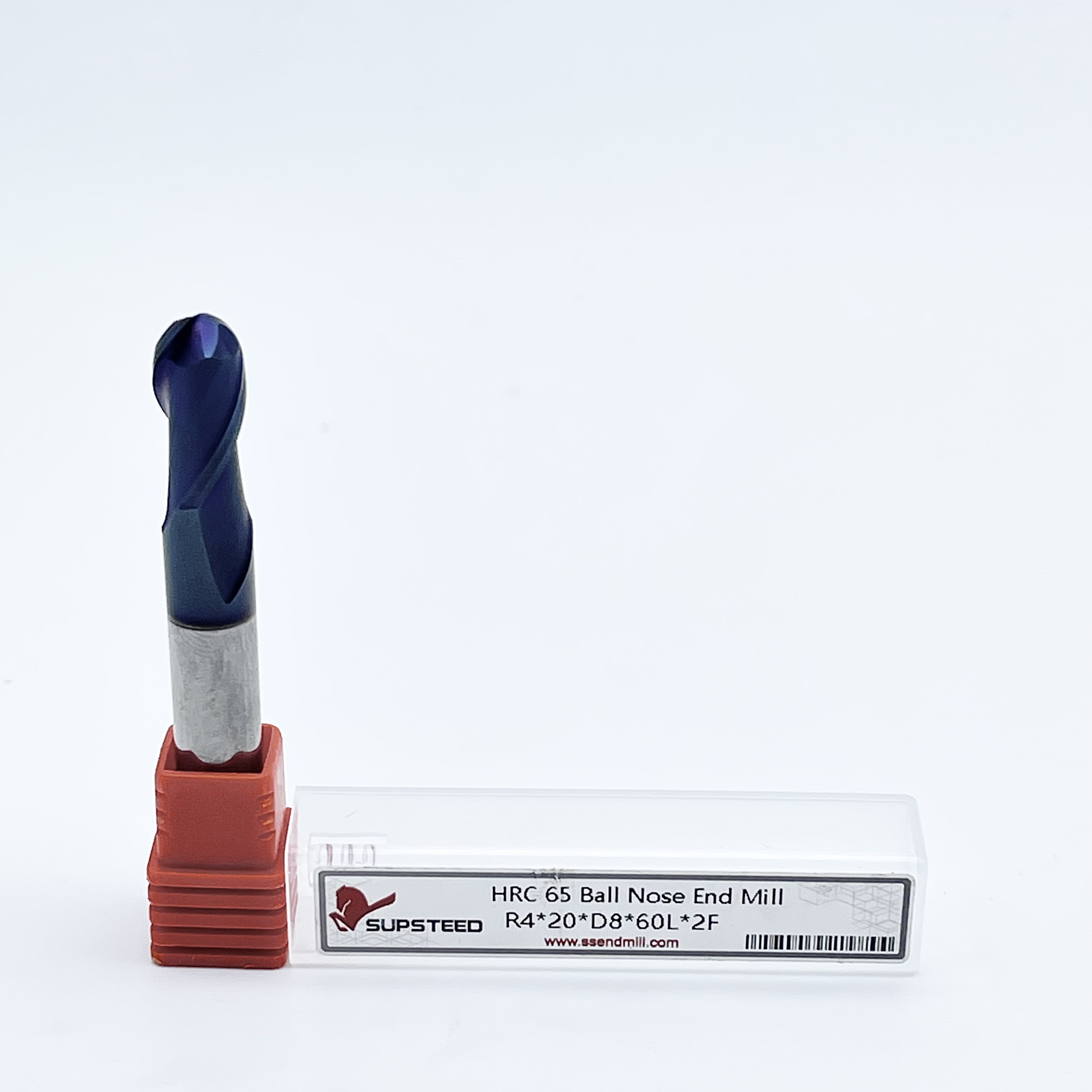
Ball Nose End Mills feature a perfectly hemispherical tip. This makes them the undisputed industry standard for 3D profiling, complex mold making, and achieving superior surface finishes on organic free-form curves.
Corner Radius End Mills blend a flat bottom geometry with precisely rounded corners. This robust design provides exceptional edge strength, making them ideal for high-feed applications and aggressive roughing operations.
Tool life is generally much longer for a bull-nose geometry due to its reinforced cutting edge. Conversely, spherical-tipped tools require precise CAM programming to circumvent zero-surface-speed issues at the dead center of the tool.
The final choice between these two geometries hinges entirely on your specific toolpath requirements. Rely on spherical cutters for sweeping 3D topologies, and utilize corner-radiused tools for flat-bottomed pockets with filleted walls.
In modern manufacturing, the geometry of the cutting tool dictates every single aspect of the milling process. It controls everything from bulk material removal rates to the final micro-inch surface finish. Selecting the correct shape is not a programmer preference. It is a strict mechanical necessity rooted deep in the physics of metal cutting.
The profile of the cutting edge determines exactly how a tool engages with the raw workpiece. When a flute bites into the material, it generates significant shearing forces and intense thermal loads. The exact geometry of the tip dictates how those forces are distributed across the substrate of the tool. Proper force distribution prevents dangerous tool deflection, minimizes harmonic vibration commonly known as chatter, and ensures crisp chip evacuation. Using an inappropriate tip shape concentrates stress on a fragile point, inevitably leading to catastrophic tool failure mid-cycle.
While cutting tools can certainly be manufactured from High-Speed Steel or cobalt, solid carbide cutter solutions are the definitive industry standard for contemporary production environments. Tungsten carbide offers extreme rigidity, exceptional wear resistance, and the crucial ability to withstand the blistering temperatures generated during high-speed dry machining. For geometries that require maintaining precise microscopic radii over hours of continuous cutting, the inherent hardness of solid carbide ensures the tool retains its exact factory shape over a highly profitable operational lifespan.
A spherical-tipped tool is highly specialized. It is engineered specifically to tackle organic shapes, sweeping aerodynamic curves, and multi-axis contouring where traditional flat tools would leave unacceptable gouges or jagged steps in the workpiece.
The defining physical characteristic of a ball nose end mill is its fully rounded tip. The cutting edge forms a perfect, continuous hemisphere at the bottom of the flute. Mathematically speaking, the radius of this hemisphere is exactly half of the total diameter of the cutter. A 10mm diameter tool will feature a continuous 5mm radius at its tip. This uninterrupted curve means there are no sharp corners to chip under load. However, it also fundamentally alters how the tool shears metal compared to a standard square end mill.
The most critical engineering challenge with this specific geometry lies at the very tip. Machinists refer to this area as the dead center. In milling operations, cutting speed or surface footage is calculated based on the effective diameter of the tool actively engaged in the cut. Because the very center point of the hemispherical tip has an effective diameter of absolute zero, the surface speed at that exact microscopic point is also zero.
Consequently, when the dead center engages the raw material, it does not shear or cut cleanly. It aggressively rubs and plows. This friction generates excessive heat and dramatically accelerates tip wear. To counteract this physical limitation, savvy machinists program toolpaths with a slight tilt angle in 5-axis machining. Alternatively, they utilize lead and lag angles to ensure the tool cuts with the faster-moving side of the ball rather than the stagnant dead center.
Despite the dead center challenge, these cutters remain absolutely indispensable. Their primary advantage is the unparalleled ability to create incredibly smooth, flowing curves on complex free-form surfaces. The cutting edge is perfectly continuous, leaving a highly consistent finish across wildly varying Z-axis elevations. This makes it the ultimate finishing weapon for high-tolerance mold making, intricate die casting, and aerospace turbine blade manufacturing.
Often referred to colloquially as a bull-nose tool, this hybrid geometry brilliantly bridges the functional gap between a standard square end mill and a full spherical cutter. It offers a unique, highly sought-after combination of structural strength and flat-bottom cutting capability.
Unlike the full hemisphere of its counterpart, a corner radius end mill features a predominantly flat bottom. Instead of the sharp, fragile 90-degree intersection found on standard square end mills, the outer edges are precision-ground with a specific fillet. For instance, a robust 12mm diameter tool might feature a flat bottom transitioning into a 1mm radius on the corners. This clever design allows the tool to aggressively machine flat floors while simultaneously leaving a smooth, radiused transition along the adjoining vertical walls.
The primary engineering benefit of this radiused design is sheer mechanical strength. On a razor-sharp square end mill, the 90-degree corner is undeniably the weakest point of the tool. That sharp edge is highly susceptible to micro-fractures and catastrophic chipping during heavy roughing cuts. By introducing a calculated radius, the immense cutting forces are distributed over a significantly larger surface area. This critical reinforcement protects the delicate carbide edge, empowering the tool to withstand much higher feed rates and heavier chip loads without prematurely failing.
The real-world advantages of this geometry focus heavily on high-efficiency material removal and preserving part integrity. First, it offers vastly superior tool life and accommodates highly aggressive roughing parameters. Furthermore, leaving a filleted inside corner in a deep machined pocket significantly reduces stress concentrations in the final manufactured part. This is a non-negotiable structural requirement in aerospace, medical, and automotive engineering applications.
When a mechanical component features undulating surfaces, complex organic topologies, or sweeping aerodynamic profiles, 3D contour milling is the required strategy. In this demanding domain, the full radius geometry stands as the undisputed champion.
In true 3D profiling, the CNC machine must simultaneously interpolate the X, Y, and Z axes in fluid motion. A flat-bottom tool deployed here would leave distinct, ugly stair-step marks across angled surfaces. It would almost certainly gouge the material when transitioning from a shallow flat area to a steep vertical wall. The spherical tip effortlessly navigates these transitions. The point of contact between the spinning tool and the workpiece smoothly glides along the radius as the slope changes, ensuring a continuous, gouge-free surface.
Achieving a mirror-like surface finish in 3D applications requires a deep practical understanding of stepover and cusp height. Stepover is simply the lateral distance the tool moves over for each successive parallel pass. Because the profile of the tool is round, these parallel passes inevitably leave behind tiny microscopic ridges of uncut material known as cusps or scallops.
To minimize this cusp height and drastically improve the surface finish, programmers must tighten the stepover distance. The relationship between tool diameter, stepover, and resulting cusp height is governed by precise trigonometry. Using larger diameter tools combined with exceptionally small stepovers yields the smoothest possible finishes. This exact technique frequently eliminates the expensive need for manual hand-polishing in mold and die shops.
Creating a 90-degree step in a workpiece involves cutting a flat surface and a vertical wall simultaneously. This fundamental machining operation is known as shoulder milling, and it demands a robust tool that can handle severe radial and axial loads efficiently without deflecting.
High-Efficiency Milling is a modern, highly profitable machining strategy. It utilizes a massive axial depth of cut paired with a very light radial depth of cut. This advanced technique spreads the abrasive wear evenly across the entire flute length, but it places immense mechanical stress on the bottom corners of the tool. A bull-nose tool is the absolute perfect candidate for dynamic toolpaths. The robust, rounded corner stubbornly resists the chipping that would instantly obliterate a sharp square tool under those exact same aggressive roughing parameters.
Unlike spherical-tipped tools, the center of a corner radius cutter is perfectly flat. This allows it to shear and clear material rapidly on the floor of a part, acting much like a traditional square end mill. As the flat center shears the floor material, the radiused outer edge simultaneously sweeps the vertical wall. This leaves a clean, precise shoulder with the required structural fillet at the intersection.
Recent developments in the manufacturing sector highlight a massive shift toward dynamic toolpaths and high-speed 5-axis machining. The electric vehicle and aerospace sectors are driving a massive surge in demand for tooling capable of machining exotic alloys like Titanium and Inconel. In these high-stress environments, minimizing cycle time while stabilizing tool life is the primary goal.
Consequently, industry data shows a sharp increase in the adoption of corner-radiused tools for high-efficiency roughing. The reinforced geometry allows shops to push feed rates to the absolute limit of their machine spindles without fearing sudden tool breakage. Meanwhile, high-hardness spherical tools remain strictly reserved for the final micro-finishing passes on complex molds and turbine blades.
To make a highly informed purchasing and CAM programming decision, review this direct comparison across key manufacturing performance metrics.
Performance Metric | Ball Nose End Mill | Corner Radius End Mill |
|---|---|---|
Material Removal Rate | Low. Best suited for light finishing passes. | Extremely High. Ideal for aggressive roughing. |
Surface Finish on 3D Curves | Superior. Leaves a seamless, flowing finish. | Poor. Leaves large stair-steps on steep slopes. |
Flat Floor Capability | Inefficient. Prone to center rubbing and smearing. | Excellent. Shears flat floors rapidly and cleanly. |
Tool Life Durability | Moderate. Requires tilt angles to prevent tip wear. | Exceptional. Corner fillet distributes stress evenly. |
Selecting the optimal tool geometry requires carefully analyzing your specific workpiece, deeply understanding the rigid capabilities of your machine, and sourcing reliable high-performance tooling based on exact material specifications.
The decision tree becomes highly actionable when you match geometry with material parameters. If you are machining hardened tool steels up to HRC65, tool rigidity is paramount.
Opt for a Spherical Tip: Use this geometry if the part features sweeping organic curves, complex 3D mold cavities, or demands a continuous mirror-like finish across varying Z-heights. For extremely hard materials, specify an HRC65-rated tool with a micro-grain carbide substrate to ensure the tip does not deform under high thermal loads.
Opt for a Bull-Nose: Select this geometry if the part contains deep structural pockets, straight vertical walls, expansive flat floors, or requires heavy bulk material removal prior to final finishing. The reinforced corner is mandatory for dynamic roughing in tough alloys.
In high-production CNC manufacturing, it is rarely a strict choice between one or the other. Profitable shops utilize a hybrid tooling approach to maximize spindle efficiency. A standard workflow involves roughing out a massive 3D mold block using a large-diameter radiused tool to rapidly clear bulk material. Once the part is aggressively stepped out, the machinist seamlessly switches to a smaller spherical tool. This tool executes the fine 3D finishing passes, effortlessly wiping away the remaining stair-steps left by the roughing cycle.
Regardless of the specific geometry you ultimately choose, the raw quality of the carbide substrate and the applied coating will dictate your success on the machine. It is crucial to invest in premium solid carbide solutions that feature advanced high-performance coatings like Titanium Aluminum Nitride or Aluminum Titanium Nitride. These specialized coatings provide a vital thermal barrier, allowing the cutting edge to withstand the blistering heat of dry machining or high-speed dynamic contouring.
Ready to optimize your machining process, eliminate chatter, and drastically reduce cycle times? Choosing the exact right geometry and coating makes all the difference on the shop floor. Visit https://www.ssendmill.com to explore an extensive catalog of precision-ground end mills. Whether you need HRC65-rated ball nose cutters for hardened mold steel or heavy-duty corner radius tools for titanium roughing, you will find the exact industrial tooling required to guarantee tighter tolerances and a flawless surface finish on every single part.
Yes, but its application is usually limited to very shallow curves or aggressive 3D roughing operations designed to step out bulk material. For steep or complex 3D profiles, a flat-bottom radiused tool will likely gouge the material or leave massive stair-steps. A spherical-tipped tool remains the far better choice for final 3D finishing.
The very center point of a spherical tool has an effective cutting diameter of zero, meaning its cutting surface speed is also zero. When fed straight down into material, it tends to rub, plow, and generate massive friction rather than cleanly shearing the metal. This leads to rapid thermal wear unless the programmer utilizes a tilt angle to cut with the side of the tool.
In the vast majority of heavy machining scenarios, yes. The rounded corner physically protects the most fragile, vulnerable part of the carbide flute from chipping. This geometric reinforcement significantly extends tool life, especially during heavy roughing and dynamic milling toolpaths.
Stepover is mathematically calculated based on your maximum allowable cusp height, also called scallop height, and the specific diameter of the tool. Smaller stepovers with larger diameter tools yield the smoothest possible finishes in 3D profiling, though they will proportionally increase your overall machine cycle time.
When machining hard metals, the ideal stepdown depends heavily on your dynamic milling strategy. For High-Efficiency Milling, machinists typically use a deep axial depth of cut, up to two times the tool diameter, paired with a very light radial stepover of five to ten percent. This utilizes the entire flute length and relies on the radiused corner to absorb the entry shock.
Tool runout is catastrophic during 3D finishing. Even a few ten-thousandths of an inch of runout will cause one flute to take a heavier chip load than the others. On a spherical tip, this uneven cutting force creates visible chatter marks and degrades the surface finish, completely defeating the purpose of using a high-precision finishing tool.
Micro-grain solid carbide is highly recommended for both of these geometries. Due to its extreme structural rigidity, high heat tolerance, and incredible ability to hold a razor-sharp edge significantly longer than traditional tool steels, it is the undisputed standard for modern CNC applications.