- All
- Product Name
- Product Keyword
- Product Model
- Product Summary
- Product Description
- Multi Field Search

Views: 0 Author: Site Editor Publish Time: 2026-08-07 Origin: Site

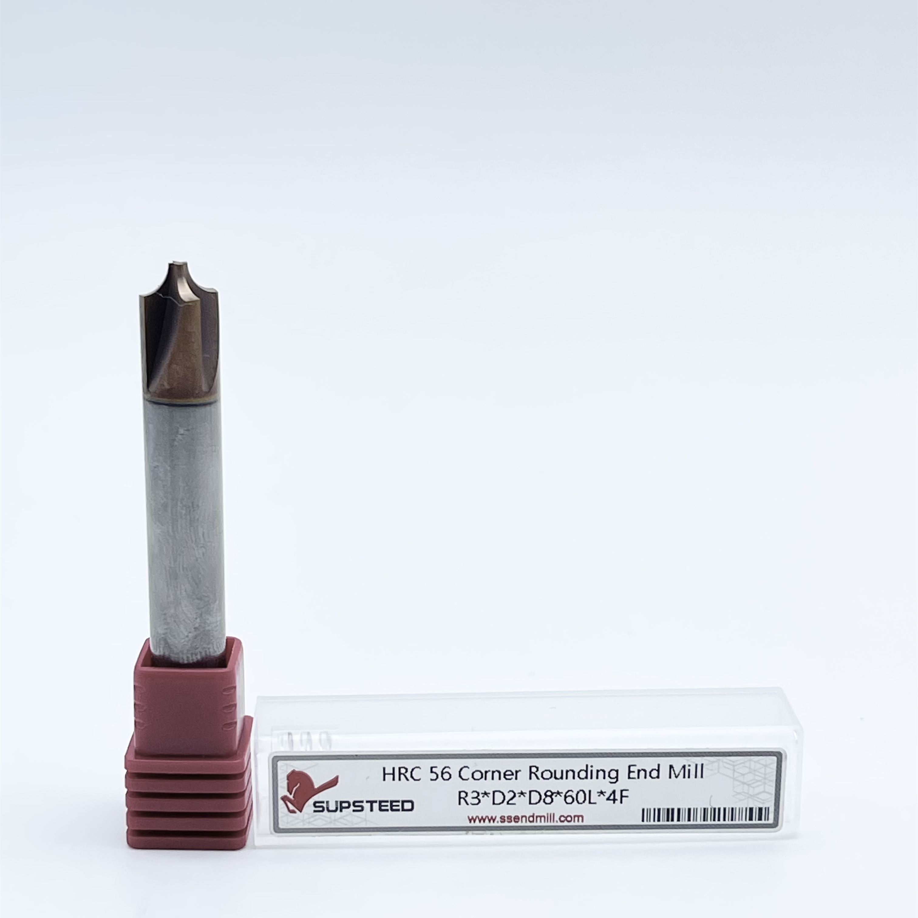
Edge finishing operations typically occur at the end of the machining cycle. Selecting the wrong tool for this final step risks scrapping a nearly completed, high-value part due to chatter, poor surface finish, or dimensional inaccuracy. Machinists frequently attempt to use a one-size-fits-all approach to edge profiling. However, aluminum and steel possess fundamentally different metallurgical properties. Aluminum is prone to galling and requires aggressive chip evacuation, while steel generates high heat and demands maximum tool rigidity. Selecting the correct corner rounding end mills requires evaluating specific tool geometries, flute counts, pilot diameters, and material-specific coatings to match the exact demands of the workpiece and the machine setup.
Before specifying a tool for a specific metal, engineers must understand the anatomical variables that dictate a tool's performance envelope and failure limits. Edge profiling applies unique radial forces to the spindle. You need a solid grasp of tool anatomy to optimize feeds and speeds properly.
The radius size serves as the primary dimension dictating the final part profile. You must match it exactly to part print tolerances. For delicate finishing operations on thin-walled aerospace components, smaller radii often work best. Radii between 0.2mm and 1.0mm minimize radial tool pressure. This prevents thin-walled parts from deflecting during the final pass. Conversely, larger radii handle heavy structural edge breaking on mold bases or heavy equipment frames. They require rigid setups, shrink-fit tool holders, and high-torque spindles to overcome the increased cutting resistance.
The pilot diameter acts as the structural foundation for the cutting edge. It represents the flat, non-cutting bottom section of the tool. A robust pilot diameter stabilizes the cutting action. It resists the lateral forces generated during heavy profiling. When you machine tough alloys like 4140 steel, a weak pilot diameter will flex, causing immediate chatter. The major diameter represents the widest part of the cutting tool. It determines your required spindle speeds. It also dictates the physical clearance requirements around clamps, fixtures, and adjacent part features. You calculate your surface footage based on this major diameter, not the pilot.
The interface between the machine spindle and the cutting tool plays a massive role in profiling success. Standard ER collets offer decent gripping force, but they often introduce runout. When a profiling tool runs out of concentricity, one flute takes a heavier chip load than the others. This uneven cutting action generates harmonic vibrations. For high-precision edge finishing, upgrade to hydraulic chucks or shrink-fit tool holders. These systems provide 360-degree clamping force and virtually eliminate runout. The increased rigidity allows you to maximize feed rates while maintaining a pristine surface finish.
To ensure accurate profiling, follow these tool verification steps before hitting cycle start:
A common point of confusion involves tool application. Machinists often wonder when a specialized profiling tool outperforms a standard square end mill. Corner rounding tools profile the outside edges of a part in a single pass. They wrap around the exterior corner to create a perfect radius. Conversely, square end mills featuring a corner radius handle inside corners. We often call these bullnose end mills. You use them for flat-bottom pockets in molds and dies.
Utilizing the correct tool for external contours drastically cuts cycle times. It eliminates the need for complex 3D surfacing toolpaths. A 3D ball-nose surfacing path might take ten minutes to interpolate a smooth edge. A dedicated profiling cutter finishes the same edge in seconds. This approach also improves the final surface finish. It removes the tiny scallop marks left behind by multi-pass 3D surfacing operations.
Unflared designs feature a radius stopping exactly at 90 degrees. They work best for simple edge breaking. You use them when blending into a side wall is not required. However, unflared tools carry a specific risk. They easily leave a visible witness mark along the part edge. If your Z-axis offsets are not perfectly dialed in, the sharp transition point digs into the material.
Flared designs solve this blending issue. They feature a slight over-cut past the 90-degree tangent. This flare typically measures between 3 and 5 degrees. The over-cut geometry proves essential for precision applications. It creates a smooth, step-free blend between the machined radius and the adjacent vertical wall. Flared tools offer a wider margin for error during machine setup. They forgive minor discrepancies in tool length offsets.
The physical geometry of the tool must match the target material. You must evaluate the chip formation characteristics of the metal. You also need to consider the specific stage of machining. Roughing passes demand different geometries than final finishing passes. Proper geometric selection prevents catastrophic tool failure and ensures predictable wear patterns.
Aluminum produces large, stringy chips during the cutting process. It possesses a low melting point and high ductility. Specify 2- or 3-flute tools for aluminum applications. Lower flute counts provide maximum gullet space. This open geometry prevents chip packing. When chips pack into the flutes, they weld to the cutting edge. This leads to immediate tool breakage and scrapped parts. We often see machinists try to run 4-flute tools on 6061-T6 aluminum to increase feed rates, but the tight gullets inevitably clog.
Steel behaves entirely differently. It produces smaller, hotter chips. It requires significant shear force to sever the material. Specify 4-, 5-, or 6-flute tools for steel alloys. Higher flute counts increase the core diameter of the tool. A thicker core adds massive rigidity. This rigidity combats the high cutting forces generated by ferrous metals. More flutes also allow for higher feed rates. This maintains productivity while distributing the heat load across multiple cutting edges.
Edge profiling inherently carries a high deflection risk. These tools cut on a varying diameter along the radius. This geometry creates uneven radial pressures. The pressure pushes the tool away from the workpiece. If the tool deflects, it leaves a tapered or undersized radius. Deflection also induces severe chatter, destroying the surface finish.
Always apply a strict selection rule. Select the largest pilot diameter that fits within the part's physical constraints. You must avoid clamps, fixtures, or adjacent tall features. A larger pilot exponentially increases the tool's cross-sectional strength. It anchors the cutting edge firmly against the material. When you maximize the pilot diameter, you minimize vibration. This allows you to push the tool harder and achieve a mirror-like finish.
The stage of machining dictates your tool requirements. Heavy roughing of large external radii demands robust solutions. You should utilize indexable tools or maximum-flute solid carbide cutters. These tools withstand massive cutting forces. They remove bulk material quickly without fracturing.
Finishing passes require a completely different approach. You need high-concentricity solid carbide tools. The tool must feature precise radius tolerances to ensure a flawless blend and superior surface finish. A dedicated finishing cutter should take a very light radial step-over. Never use your roughing cutter for the final finishing pass. The micro-chipping sustained during roughing will transfer directly onto your final part surface.
Your coolant strategy must adapt to the material and the tool geometry. When machining aluminum with a 2-flute cutter, high-pressure flood coolant is mandatory. The fluid must physically flush the stringy chips out of the wide gullets before they can recut. Aim the coolant nozzles directly at the tool-workpiece interface. Conversely, when machining hardened steel with a multi-flute coated tool, thermal shock becomes the primary failure mode. If cold coolant hits a red-hot carbide cutting edge, the carbide will develop micro-cracks and chip. For these applications, turn off the flood coolant. Use a programmable air blast to clear chips from the cutting zone while allowing the coating to manage the heat.
Tool Selection Parameters for Aluminum vs. Steel
| Material Category | Optimal Flute Count | Recommended Coating | Pilot Diameter Strategy | Coolant Application |
|---|---|---|---|---|
| Aluminum Alloys | 2 to 3 Flutes | ZrN, TiB2, or Polished Uncoated | Maximum allowable for part clearance | High-pressure flood coolant |
| Carbon & Alloy Steels | 4 to 6 Flutes | AlTiN, TiAlN | Maximum allowable for rigidity | Air blast or light mist |
| Stainless Steel | 4 to 5 Flutes | AlTiN (High performance) | Moderate to large (avoid rubbing) | High-pressure flood coolant |
Carbide alone cannot withstand the extreme environments of modern CNC machining. Tool coatings act as a thermal barrier and a lubricity enhancer. However, applying the wrong coating causes more harm than using bare carbide. You must match the coating chemistry to the workpiece metallurgy.
Aluminum presents a unique chemical challenge. It readily bonds to other metals under heat and pressure. You must strictly avoid AlTiN (Aluminum Titanium Nitride) or TiAlN coatings. These coatings contain aluminum. When machining aluminum parts, the heat causes the workpiece material to weld directly to the coating. This creates a built-up edge (BUE). The BUE alters the tool geometry, causes severe galling, and eventually snaps the cutter.
Instead, specify ZrN (Zirconium Nitride) or TiB2 (Titanium Diboride) coatings. These options provide exceptional lubricity. They prevent aluminum chips from sticking to the flutes. Alternatively, use uncoated, highly polished solid carbide. A mirror-polished flute allows stringy aluminum chips to slide out of the cutting zone effortlessly. Polished carbide remains the industry standard for aerospace aluminum finishing.
Steel machining generates intense heat at the cutting edge. Uncoated carbide degrades rapidly under these thermal loads. You need coatings designed to thrive in high-temperature environments. AlTiN and TiAlN excel in steel applications. As the cutting temperature rises, these coatings form a microscopic layer of aluminum oxide. This oxide layer shields the carbide substrate from thermal shock.
For hardened steels or tool steels, consider advanced nanocomposite coatings. These coatings maintain their hardness even at red-hot temperatures. They allow you to run the corner rounding cutter dry or with minimal air blast. Dry machining steel often improves tool life. It prevents the thermal cracking caused by cold coolant hitting a hot cutting edge.
Even with the perfect tool, edge profiling presents operational challenges. Machinists often encounter issues during the first-article run. Recognizing the symptoms of poor cutting dynamics allows you to adjust parameters quickly. You can salvage the part and optimize the process for the remaining production run.
Chatter manifests as a visible, rippled pattern on the machined radius. It sounds like a high-pitched squeal during the cut. Chatter destroys surface finish and rapidly dulls the cutting edge. It usually stems from a lack of rigidity in the setup. To eliminate chatter, first check your tool overhang. Choke the tool up in the collet as much as possible. Excessive stick-out acts like a tuning fork. Next, evaluate your feed rate. Machinists often reduce the feed rate when they hear chatter. This actually makes the problem worse. A low feed rate causes the tool to rub rather than cut. Increase your feed per tooth to stabilize the tool pressure. Finally, ensure you selected the largest possible pilot diameter to maximize core strength.
Follow this sequence to eliminate chatter during edge profiling:
A witness mark is a visible line where the radius meets the flat surface of the part. It ruins the aesthetic appeal of a finished component. This issue almost always relates to Z-axis positioning or tool geometry selection.
If you use an unflared tool, your tool length offset must be perfect down to the micron. Even a 0.01mm error leaves a step. To fix this, switch to a flared profile tool. The slight over-cut blends the radius naturally into the wall. If you must use an unflared tool, program a microscopic Z-axis shift. Raise the tool by 0.02mm to blend the top edge smoothly without gouging the vertical wall.
Built-up edge occurs when workpiece material pressure-welds to the cutting face. It primarily affects aluminum and gummy stainless steels. BUE effectively changes the geometry of your tool. It turns a sharp cutting edge into a blunt, tearing instrument.
To resolve BUE in aluminum, verify your coating selection. Ensure you are not using an AlTiN coated tool. Next, check your coolant concentration and pressure. You need high-pressure flood coolant aimed directly at the cutting zone. The coolant provides lubricity and physically blasts the chips away. If BUE persists, increase your surface footage (RPM). Higher speeds generate enough localized heat to shear the chip cleanly before it can weld to the carbide.
The way you drive the tool through the material matters just as much as the tool itself. CAM programming strategies heavily influence tool life and part quality. You must apply specific toolpath techniques to maximize the efficiency of your profiling operations.
Always default to climb milling for edge profiling operations. In climb milling, the cutting edge engages the material at maximum thickness and exits at zero thickness. This directs the cutting forces down into the fixture. It holds the part securely and yields a superior surface finish.
Conventional milling engages the material at zero thickness and rubs before it begins to cut. This rubbing generates massive friction. It causes rapid tool wear and pushes the part away from the tool. Only use conventional milling if your machine suffers from severe backlash or if you are cutting cast iron with a heavy abrasive scale. Modern CNC equipment should always utilize climb milling for external radii.
Never plunge the tool directly into the part edge. A direct plunge spikes the radial load instantly. It leaves a deep gouge mark at the entry point. It also risks chipping the delicate corner of the cutting flute.
Program a smooth arc lead-in. Roll the tool into the cut using a radius slightly larger than the tool diameter. This gradually increases the radial engagement. The tool stabilizes before it reaches the full depth of cut. Apply the same logic to the exit. Program an arc lead-out to sweep the tool away from the finished surface gently. This technique guarantees seamless transitions and extends tool life significantly.
When dealing with large radii on tough materials like 4140 pre-hardened steel, a single pass often exceeds the horsepower limits of the machine or the rigidity of the setup. In these cases, program a multi-pass toolpath. Start by roughing the corner with a standard square end mill or a chamfer tool to remove the bulk of the material. This leaves a faceted edge. Then, bring in your profiling tool for a semi-finish pass, leaving 0.005 inches of stock. Finally, execute a spring pass at the final dimension. This multi-step approach drastically reduces radial tool pressure, eliminates chatter, and extends the life of your expensive finishing tools.
When programming your toolpaths, calculating the correct surface footage requires attention to the tool's varying diameter. Because a corner rounding tool cuts along a curve, the effective cutting diameter changes constantly. The major diameter spins faster than the pilot diameter. If you calculate your RPM based on the pilot diameter, the major diameter will exceed the recommended surface footage, burning up the outer edge of the tool. Always use the major diameter for your RPM calculations to keep the maximum cutting speed within safe limits.
Additionally, consider the chip thinning effect. When taking a light radial step-over for a finishing pass, the actual chip thickness is less than the programmed feed per tooth. To compensate for this, you must increase your programmed feed rate. If you fail to adjust for chip thinning, the tool will rub against the material, generating excess heat and accelerating flank wear.
A: An unflared profile stops exactly at a 90-degree tangent, making it suitable for simple edge breaking. A flared profile includes a 3 to 5-degree over-cut past the tangent. This flare allows the tool to blend the radius smoothly into an adjacent vertical wall without leaving a visible witness mark.
A: We highly discourage it. Aluminum produces large, stringy chips that require significant gullet space for evacuation. A 4-flute tool has tight gullets, which causes aluminum chips to pack, weld to the cutter, and eventually snap the tool. Always use 2- or 3-flute tools for aluminum.
A: A visible step, or witness mark, usually results from inaccurate Z-axis tool length offsets. It also happens frequently when using unflared tools. To fix this, dial in your tool offsets precisely or switch to a flared corner rounding tool to create a forgiving, seamless blend.
A: Calculate your spindle speed based on the major diameter of the tool, not the pilot diameter. The major diameter represents the fastest-moving point of the cutting edge. Using the smaller pilot diameter for calculations results in excessive surface footage, leading to rapid tool wear.
A: Always use climb milling on modern CNC machines. Climb milling directs cutting forces into the workpiece and fixture, reducing vibration. It cuts the chip from thick to thin, which minimizes heat generation, prevents work hardening, and produces a far superior surface finish.
A: Chatter is caused by a lack of rigidity. Common culprits include excessive tool stick-out from the holder, selecting a tool with a pilot diameter that is too small, or running a feed rate that is too low. Choke up the tool, maximize the pilot diameter, and maintain proper chip loads.