Please Choose Your Language
- All
- Product Name
- Product Keyword
- Product Model
- Product Summary
- Product Description
- Multi Field Search

Views: 0 Author: Site Editor Publish Time: 2026-09-16 Origin: Site

Mold and die manufacturing leaves zero room for error. Precision and surface finish are non-negotiable on the shop floor. Machinists operate under intense pressure where a single miscalculation can scrap a highly valuable block of tool steel. Today, manufacturers must produce complex geometries that demand flawless surface integrity. The ultimate goal is to minimize or entirely eliminate manual polishing.
Achieving these exacting results depends directly on your cutting tool strategy. CNC programmers constantly face a specific dilemma when generating 3D toolpaths. They must decide between a ball profile and a flat-bottomed tool with radiused corners. Both are foundational to the industry. However, they possess distinct geometric characteristics that dictate their performance across different topographies.
There is no universal solution. The right choice depends entirely on the specific geometry of the mold cavity, the current machining stage, and the hardness of the workpiece. This guide provides an empirical, frontline engineering comparison of these essential tools. It is designed to help tooling buyers and machinists optimize toolpaths, improve surface finishes, and extend cutter life during demanding applications.
Application is Everything: A hemispherical cutting profile is geometrically ideal for steep 3D contours. A radiused-corner flat mill excels in shallow draft angles and flat floors with filleted corners.
Tool Life Matters: Flat-bottomed radiused tools generally offer prolonged durability in tough materials. They completely avoid the zero cutting speed phenomenon inherent to the dead center of a fully rounded tip.
Surface Finish: Continuous radius tools leave smaller cusp heights on steep vertical walls. Flat-bottomed tools leave mathematically superior finishes on relatively flat or gently sloping topographies.
Material Selection: High-grade solid carbide substrates equipped with advanced thermal coatings are mandatory. Both tool types need this to withstand the intense heat and abrasive wear inherent in modern mold making.
The mold and die sector presents unique machining challenges rarely seen in standard production environments. Picture a complex injection mold for an automotive dashboard. It features deep cavities, intricate organic shapes, fragile thin ribs, and highly complex parting lines. The primary objective is to machine these features as close to the final net shape as possible.
Any dimensional deviation or poor surface finish mandates manual benching. This secondary polishing operation introduces human error, alters precise mathematical tolerances, and drastically inflates production costs. Getting the toolpath right the first time is a fundamental engineering requirement.
Unlike general engineering components, mold bases and core inserts are frequently machined in their fully hardened state. Materials like P20, H13, and D2 tool steels are routinely milled at hardness levels ranging from HRC 45 to 65. Cutting in this hardened state effectively prevents the dimensional distortion that typically occurs during post-machining heat treatment.
Standard high-speed steel tools will fail catastrophically under these extreme conditions. The immense localized heat generated at the cutting edge causes rapid thermal degradation. Navigating the complexities of hardened steel machining requires micro-grain solid carbide. This material provides the hot hardness and core rigidity necessary to shear tough alloys without shattering.
When selecting tools for mold cavities, machinists must constantly balance three competing metrics. These are Material Removal Rate, tool longevity, and final surface finish. Pushing for maximum removal rates reduces machine cycle times but increases cutting forces. This can prematurely degrade the cutting edge. Prioritizing surface finish often requires micro-stepovers and lower feed rates, inherently extending cycle times. The correct geometric choice directly influences a shop's ability to optimize this operational triad.
A ball nose cutter features a cutting end with a full continuous radius exactly equal to half of the tool's overall diameter. This sweeping hemispherical geometry means there are no sharp corners. The cutting edge transitions smoothly from the shank down to the exact center of the tool.
When evaluating this profile, its true strength shines in adaptability. It is the definitive tool for simultaneous 5-axis machining and complex 3D profiling. Because the cutting edge is a continuous curve, it can engage the workpiece from almost any vector. Applied to steep walls, the geometry creates smooth sweeping contours. It leaves predictable, easily manageable cusp heights that follow the topography of the mold flawlessly.
Despite its versatility, this tool suffers from a significant mechanical flaw known as the dead center problem. At the exact bottom tip of the hemisphere, the effective cutting diameter is zero. As a result, the surface cutting speed at this specific point is also zero.
If you drive the tool straight down into a workpiece or attempt to face a perfectly flat horizontal floor, the center of the tool does not shear the material. Instead, it extrudes and rubs against the steel. If you have ever heard the high-pitched squeal of a tool rubbing against hardened D2, you are witnessing this exact phenomenon. This friction generates excessive heat, leads to smeared surface finishes, and causes rapid tip wear.
Even with the dead-center limitation, this geometry remains indispensable. It is best utilized for final finishing of deep, steep-walled cavities. It is also perfect for profiling complex core pins and tracing intricate 3D parting lines where maintaining a constant radius is mathematically required by the CAD model.
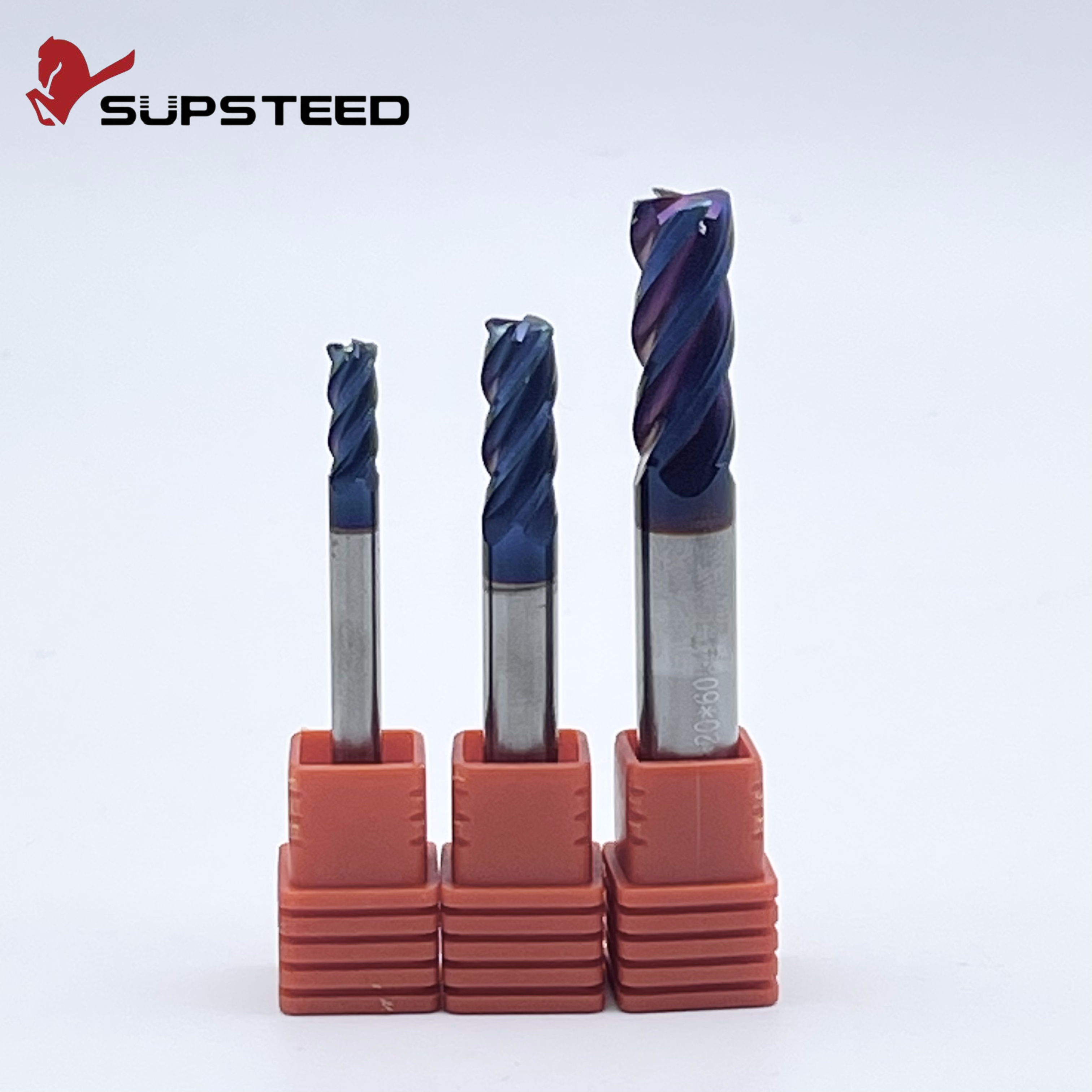
Often referred to within the trade as a bull nose end mill, a corner radius mill features a flat bottom geometry that transitions into a specific, defined radius on the outer cutting corners. Unlike a full hemisphere, this radius is substantially smaller than half the tool diameter. For instance, a 12mm diameter end mill might feature a modest 1mm or 2mm corner radius, leaving a broad flat cutting area in the center.
This specific design offers exceptional structural integrity. By replacing the fragile sharp tip of a standard square end mill with a reinforced radius, cutting forces are distributed evenly across a larger surface area. This effectively prevents the corner chipping that plagues sharp tools in tough materials.
Furthermore, the flat bottom generates actual surface cutting speed across the floor of the cut. This entirely eliminates the dead-center rubbing issue. This flat geometry also allows machinists to program significantly larger radial stepovers on flat or shallow-draft surfaces, drastically reducing overall cycle times.
While highly efficient on flats, this tool is less effective on steep vertical walls. When contouring severe inclines, the flat bottom and small radius geometry will leave pronounced stair-step cusps compared to a fully rounded tool. Removing these pronounced ridges requires more intensive, time-consuming secondary finishing passes.
These tools are the empirical choice for high-efficiency roughing, semi-finishing, and finishing of flat mold floors. They are also ideal for shallow 3D features and open pockets where aggressive material removal is the primary objective.
To facilitate data-driven decision-making, it is crucial to compare these geometries across critical machining parameters. Relying on gut feeling is no longer viable in modern CNC environments. Empirical data must drive toolpath strategies.
Machining Parameter | Ball Profile Cutter | Flat-Bottom Radiused Mill |
|---|---|---|
Optimal Surface | Steep walls greater than 45 degrees, complex 3D | Flat floors, shallow drafts less than 45 degrees |
Material Removal Rate | Lower due to tight stepover limits | Higher due to wider stepovers |
Tool Wear Pattern | Concentrated at the tip with rubbing risk | Evenly distributed across the corner radius |
Bottom Cutting Speed | Zero at dead center | High efficiency across the flat bottom |
Cusp Height on Walls | Minimal and smooth | Pronounced stair-stepping |
Surface finish in 3D milling is largely dictated by cusp height. This is the unmachined material left behind between adjacent toolpath passes. Mathematical models demonstrate a clear divergence in performance based on the surface angle. On steep inclines, a hemispherical tool leaves a significantly shallower cusp for a given stepover. Conversely, on shallow inclines and flat floors, the flat-bottomed tool yields a vastly superior finish. It sweeps the surface flat, whereas a fully rounded tool would leave distinct ridges unless an impractically microscopic stepover is applied.
When enduring heavy material removal, flat-bottomed radiused tools generally exhibit superior durability. The geometry provides a stronger, thicker core. Moreover, cutting forces are directed axially upward into the machine spindle, which is the most rigid component of the CNC machine. This dynamic reduces lateral tool deflection and allows for better chip evacuation. Ultimately, it outlasts pointed profiles that frequently suffer from thermal degradation at the tip.
On the shop floor, cycle time directly dictates profitability. A flat-bottomed tool can execute a much wider effective stepover on shallow areas while maintaining the exact same theoretical surface roughness. This significantly reduces the total length of the toolpath. It translates to fewer passes and drastically decreased machine cycle times during roughing and semi-finishing phases.
For roughing operations, the objective is uncompromising. You must maximize the Material Removal Rate. The flat-bottom radiused mill is the undisputed champion here. By utilizing HRC65 rated tools with reinforced corners, machinists can handle heavy depths of cut and aggressive feed rates without shattering. It is the ultimate tool for hogging out hardened material quickly and safely.
Semi-finishing acts as the transitional phase. The goal is to leave a uniform, predictable stock allowance for the final finishing pass. Both geometries can be successfully deployed here. Transitioning to a smaller flat-bottom tool or a larger rounded profile depends entirely on the remaining stock and the topographical complexity of the mold cavity. If the mold consists mostly of shallow drafts, stick to the flat-bottom tool.
For final finishing on highly contoured undulating 3D surfaces, the continuous rounded profile is unparalleled. When programmed with a micro-stepover, often as small as 0.05mm depending on the tool diameter, it follows organic shapes flawlessly. This precision ensures a near-mirror finish that requires minimal hand-polishing. This preserves the absolute integrity of the mold's original CAD design.
The mold and die sector is currently undergoing a massive technological shift. Recent industry analyses highlight a decisive move towards lights-out manufacturing and high-speed machining strategies. Shops are increasingly relying on automation, meaning CNC machines run unattended overnight. In this demanding environment, unpredictable tool failure is catastrophic.
Consequently, the demand for extreme process reliability has changed how shops purchase consumables. Procuring the right mold milling tools has transitioned from a basic catalog purchase to a highly strategic engineering investment. Furthermore, there is an industry-wide push to achieve zero-polishing surfaces straight from the machine. Hard milling is rapidly replacing traditional EDM processes. This trend demands impeccable tool runout, advanced CAM software, and a deep understanding of when to swap a flat-bottom radiused tool for a full hemispherical cutter to optimize cusp heights dynamically.
To mitigate the zero-surface-speed issue of rounded profiles, advanced mold makers utilize 3+2 axis or full 5-axis machining centers. They physically tilt the tool relative to the workpiece. By tilting the spindle, typically between 10 to 15 degrees, the machinist moves the contact point away from the dead center and onto the rotating side of the flute. This ensures the cutting edge engages the material with a positive active cutting speed. The result is superior finishes and drastically reduced tool wear.
Climb milling, or down milling, is universally preferred when cutting tough tool steels. In this strategy, the cutting edge engages the material at its maximum chip thickness and exits at zero thickness. This dynamic forces the intense heat generated by the cut directly into the chip, rather than allowing it to soak into the workpiece or the tool. It also directs cutting forces downward, compressing the block into the fixture to enhance rigidity.
Rather than taking slow, brutally heavy cuts, high-speed machining utilizes light radial depths of cut combined with exceptionally high feed rates and spindle speeds. By maintaining a constant chip load and utilizing trochoidal milling paths, machinists can prevent heat accumulation. This strategy keeps the tool engaged in the material for shorter, more manageable durations. This allows the substrate to remain thermally stable.
When attacking hardened molds, high-speed steel or cobalt tools simply lack the necessary rigidity. Selecting premium carbide milling tools is non-negotiable. The micro-grain structure of high-end carbide provides the stiffness required to resist lateral deflection. It also provides the extreme hardness necessary to maintain a razor-sharp cutting edge under severe abrasive wear, especially when cutting HRC65 materials.
Uncoated carbide will oxidize and break down rapidly in high-heat dry machining environments. Tools must be equipped with advanced thermal coatings like Titanium Aluminum Nitride or Aluminum Titanium Nitride. During the cut, these coatings form a microscopic protective aluminum oxide layer. This shields the carbide substrate from heat, allowing for highly efficient dry machining using only compressed air blasts to evacuate chips.
For softer materials like aluminum, 2 to 3 flutes provide the necessary deep valleys for chip clearance. However, for hardened tool steel, selecting cutters with 4 to 6 flutes is highly recommended. A higher flute count increases the tool's core diameter, maximizing overall rigidity. It also allows for significantly higher feed rates, which translates directly to a superior surface finish and less chatter.
Choosing the right cutter is a vital step in the manufacturing process. Neither geometry is universally better than the other. Rather, they are highly specialized instruments designed for specific topographical challenges. Hemispherical cutters excel on steep walls and complex 3D contours. Flat-bottom radiused mills dominate flat floors and high-efficiency roughing.
Both require high-quality solid carbide substrates and advanced coatings to survive the extreme conditions of mold making. By matching the specific tool geometry to the exact machining stage and surface angle, shops can dramatically optimize cycle times, achieve superior surface finishes, and prolong tool life. Maintaining a strategic mix of both profiles in your tool crib is the most effective way to elevate your mold and die production capabilities.
Ready to optimize your toolpaths and eliminate manual polishing? Equip your CNC machines with high-performance, precision-engineered end mills designed for the toughest tool steels. Visit ssendmill.com to explore a comprehensive range of HRC65 corner radius and ball nose milling tools tailored for your specific mold and die applications.
Yes, it is excellent for 3D contouring, especially on shallow slopes and flat floors. However, for very steep, near-vertical walls, a fully rounded profile will leave a much smoother finish with a smaller stepover cusp, requiring less secondary polishing.
The very center of this specific tool has a surface cutting speed of zero. If you plunge straight down or machine perfectly flat surfaces without tilting the spindle, the tip rubs and extrudes rather than shearing the metal. This intense friction leads to rapid thermal degradation, especially in hardened tool steels.
Absolutely. Mold and die components are frequently machined from pre-hardened or fully hardened tool steels like P20, H13, or D2. Solid carbide substrates equipped with heat-resistant coatings are structurally required to withstand the extreme cutting forces, abrasive wear, and high temperatures generated during the process.
The radius on the tool should always be slightly smaller than the smallest internal corner radius required by your mold's CAD design. If the tool radius exactly matches the corner radius, the cutter will engage 100 percent of its corner geometry simultaneously. This frequently causes severe chatter, poor finish, or catastrophic tool breakage.
For high-precision mold finishing, the stepover is typically calculated based on the desired cusp height. A standard industry practice is to use a stepover between 5 to 10 percent of the tool's diameter. For example, a 10mm tool might use a 0.5mm stepover, but for zero-polishing mirror finishes, machinists often drop this to 0.05mm or less.
Tool deflection is minimized by using the shortest possible tool overhang and selecting tools with a thicker core diameter. Using a 4-flute or 6-flute corner radius mill provides more rigidity than a 2-flute tool. Additionally, utilizing high-speed machining strategies with light radial depths of cut drastically reduces the lateral forces that cause deflection.
Generally, a flat-bottomed tool with radiused corners provides a significantly higher removal rate during roughing phases. Its robust flat bottom and reinforced corners allow machinists to program heavier depths of cut and much larger stepovers compared to a pointed or fully rounded tool.