Please Choose Your Language
- All
- Product Name
- Product Keyword
- Product Model
- Product Summary
- Product Description
- Multi Field Search

Views: 0 Author: Site Editor Publish Time: 2026-07-29 Origin: Site

Achieving a mirror-like surface finish in 3D milling requires a precise balance between cycle time and acceptable scallop height. When you machine complex contours, the rounded tip of your cutter naturally leaves behind small ridges of unmachined material between passes. These ridges are known as cusps or scallops. If you ignore them, you ruin the part's surface finish.
Excessive cusp height leads to costly, inconsistent manual polishing and benchwork. Relying on overly conservative stepovers to improve finish exponentially increases machining time. This destroys throughput and profitability. You need a strategy that optimizes the surface finish without keeping the machine running for days.
Controlling residual height requires moving beyond default CAM settings. By mathematically optimizing stepover, maximizing effective cutting diameter, and selecting material-specific tooling, machinists can reliably minimize cusp height without sacrificing operational efficiency. You can predict the exact surface roughness before the spindle even turns.
Geometry Dictates the Baseline: Tool diameter and stepover distance are the primary mathematical drivers of theoretical cusp height; utilizing the largest practical tool radius allows for wider stepovers while maintaining surface finish.
The Ultra-Finish Benchmark: For high-precision applications, target a theoretical cusp height of 0.00003" to 0.00005" (0.75 to 1.25 microns) to completely eliminate manual polishing on a mold finishing ball end mill.
Avoid the "Dead Center": The exact bottom center of a ball tool has zero surface speed. Introducing a 10–15° tool tilt engages the active cutting edge, preventing material tearing, premature tool wear, and center humps.
Recalculate Speed AND Feed: Because the tool rarely engages at its full diameter during 3D profiling, calculating the effective cutting diameter is mandatory for setting both accurate RPM and adjusted feed rates to maintain constant chip load.
Material Compatibility Matters: Theoretical cusp calculations fail if the tool edge degrades. Utilizing application-specific substrates—such as a hardened steel ball nose end mill—prevents rapid edge wear from artificially inflating surface roughness.
Cusp height is the residual, unmachined material left between adjacent toolpaths during 3D surfacing. When a spherical cutting edge moves across a flat or contoured surface, it cuts a trough. As the tool steps over to make the next pass, the intersection of these two curved troughs forms a peak. This peak is the cusp. The height of this peak directly determines the surface roughness of your final part. Machinists must understand how to manipulate this geometry to control the final output.
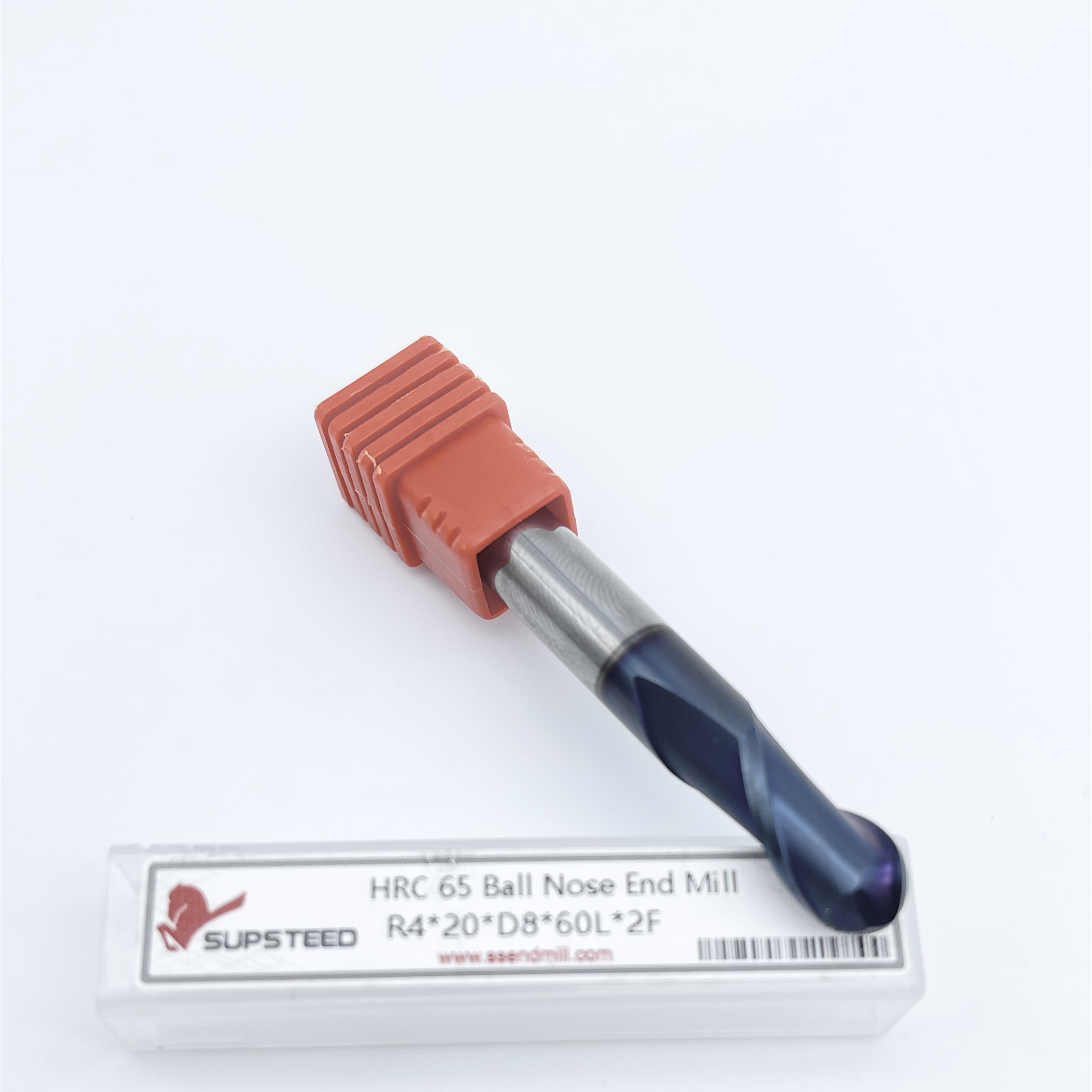
The radius of a ball nose end mill intersects with the stepover distance to create these ridges. A larger radius creates a shallower, wider trough. A smaller radius creates a deeper, narrower trough. If you keep the stepover constant but switch to a smaller tool, the cusp height increases dramatically. Understanding this geometric relationship is the foundation of 3D surfacing. You cannot guess your way to a good finish; you must calculate it.
Cusp heights spike during transitions between flat floors and vertical walls. As the tool moves up a steep wall, the effective stepover changes relative to the surface normal. A constant planar stepover in your CAM software will result in varying cusp heights across complex 3D topography. This requires precise toolpath strategies, such as 3D constant stepover or scallop toolpaths, to maintain uniform surface finishes across blending curves. We often see operators struggle with this when transitioning from 2D to 3D programming.
Frame the problem around defining an acceptable roughness average for the final part. The goal is to eliminate secondary benchwork, rather than arbitrarily chasing a zero-cusp finish. A theoretical cusp height of zero requires an infinite number of passes. By defining the maximum allowable scallop based on the part's functional requirements, you can optimize the machining time. This approach saves hours of unnecessary machine operation.
To properly evaluate cusp height on the shop floor, follow these practical steps:
Identify the maximum allowable surface roughness specified on the part print.
Convert the required roughness average into a target theoretical cusp height.
Select the largest possible tool radius that fits within the part's smallest internal geometry.
Calculate the required stepover distance to achieve the target cusp height.
Generate the toolpath and verify the stepover remains constant across steep walls and shallow floors.
Run a test cut on scrap material to verify the actual surface finish matches the theoretical calculation.
The standard calculation for cusp height relies on basic geometry. The formula is h = R - √(R⊃2; - (S/2)⊃2;), where R is the tool radius and S is the stepover distance. This equation proves that cusp height is a mathematical certainty, not a random occurrence. You can plug your desired surface finish into this formula to determine the exact stepover required for a specific tool. We use this formula daily to set up finishing passes on complex molds.
Using the largest possible ball mill yields the shortest, widest cusp for any given stepover. A larger radius flattens the curve of the cut. This allows you to increase the stepover distance while maintaining the same theoretical scallop height. Wider stepovers mean fewer passes, which drastically reduces your overall cycle time. You should always default to the largest tool the geometry permits.
However, you must balance the benefits of a large tool diameter against physical constraints. A massive cutter cannot clear tight internal radii or navigate complex part topography. If the part features a 2mm internal fillet, you cannot finish it with a 10mm ball mill. You must select the largest tool that can successfully machine the smallest features on the part, or utilize a rest-machining strategy with multiple tool sizes. This often means roughing with a large tool and finishing specific corners with a smaller one.
The exponential increase in cycle time as stepover decreases is a major production bottleneck. Dropping a stepover from 0.2mm to 0.05mm does not just double the machining time; it quadruples the toolpath length. Every fractional improvement in surface finish costs a massive amount of machine time. You must find the sweet spot where the finish is acceptable and the cycle time is profitable. Over-machining is a common way shops lose money on 3D parts.
Consider a baseline reference. If you use an R3 (6mm diameter) cutter with a 0.15mm to 0.2mm stepover, you will theoretically keep the residual height under 0.002mm. This is often sufficient for standard mechanical components. It provides a clean finish without keeping the spindle running unnecessarily long. We find this to be a reliable starting point for general-purpose 3D profiling.
High-tolerance molds require a different approach. You must scale down to a 0.00003" to 0.00005" cusp height. This ultra-finish benchmark completely eliminates manual polishing, which can alter the mold's precise geometry. Achieving this requires incredibly tight stepovers and a premium carbide ball nose end mill that will not wear down during the long finishing cycle. Tool wear will immediately ruin an ultra-fine finish.
| Tool Diameter (mm) | Stepover (mm) | Theoretical Cusp Height (mm) | Surface Finish Quality |
|---|---|---|---|
| 6.0 (R3) | 0.50 | 0.0104 | Rough / Semi-Finish |
| 6.0 (R3) | 0.20 | 0.0017 | Standard Finish |
| 6.0 (R3) | 0.05 | 0.0001 | Ultra-Fine Mold Finish |
| 12.0 (R6) | 0.20 | 0.0008 | Excellent Finish (Fast Cycle) |
| 12.0 (R6) | 0.50 | 0.0052 | Good Finish (Very Fast Cycle) |
The exact bottom center of a ball tool has zero surface speed. When the spindle rotates, the outer edges travel at the programmed surface footage, but the very tip is essentially stationary. This causes rubbing, material tearing, and rapid heat buildup. It is the primary reason machinists find a small hump left at the bottom of curved pockets or half-circle cavities. You cannot cut effectively with the dead center of the tool.
Applying a 10 to 15-degree tilt solves the zero-RPM problem. By tilting the tool via 5-axis positioning or angled fixturing, you move the contact point away from the dead center. This engages the flute's effective cutting edge. The tool actually shears the material instead of plowing through it, instantly improving the surface finish. We use this technique extensively on 5-axis trunnion machines.
Tool tilt also provides secondary benefits for chip evacuation and heat dissipation. When cutting with the side of the ball, chips flow naturally up the flutes. The cutting zone remains cooler because the active edge has a higher surface speed, which transfers heat into the chip rather than the workpiece. This extends tool life and maintains a consistent cusp height across the entire part.
Because the tool rarely engages at its full diameter during 3D profiling, calculating the effective cutting diameter is mandatory. The formula is Deff = 2 × √(R⊃2; - (R - ADOC)⊃2;), where ADOC is the axial depth of cut. If you are only cutting 0.5mm deep with a 10mm ball mill, your effective cutting diameter is much smaller than 10mm. You must account for this discrepancy.
You must adjust both spindle speed and feed rate based on this effective diameter. Running at nominal tool calculations leads to low surface footage and tool rubbing. This accelerates wear and ruins the surface finish. By recalculating the RPM based on the smaller effective diameter, you restore the proper surface speed and maintain a constant chip load. This is a critical step that many programmers overlook.
Material hardness and abrasiveness alter actual surface finish. Theoretical cusp height calculations assume a perfectly sharp tool. As the tool edge degrades, it tears the material rather than cutting it cleanly. This causes deviations from theoretical calculations and artificially inflates surface roughness. You must match the tool substrate and coating to the workpiece material to maintain edge integrity.
Profiling tool steels up to 60+ HRC generates extreme heat and cutting forces. You need a specialized hardened steel ball nose end mill to survive these conditions. These tools feature rigid micro-grain carbide substrates that resist deflection under heavy loads. Standard carbide will chip or snap when pushed into hardened P20 or H13 tool steel.
They also require high-oxidation-temperature coatings, such as AlTiN or Nanocrystalline coatings. These coatings protect the carbide from thermal shock and abrasive wear. Negative rake angles are often utilized to reinforce the cutting edge, preventing micro-chipping when engaging hardened surfaces. If the edge chips, your cusp height will immediately become irregular, leaving visible score marks on the part.
Titanium is notorious for work hardening and poor thermal conductivity. The selection criteria for a titanium ball nose end mill focus on heat management and edge sharpness. You absolutely need sharp, positive cutting edges to shear the material cleanly before it has a chance to work harden. A dull tool will push the titanium, causing the surface to harden and destroy the cutter on the next pass.
Variable helix geometries disrupt harmonic chatter, which is critical for maintaining a smooth surface finish in aerospace alloys. High-lubricity coatings, like TiAlN or AlTiCrN, prevent built-up edge. If titanium welds to the cutting edge, it alters the tool's geometry and destroys the predictable scallop height. We always run heavy coolant when finishing titanium to flush chips and prevent welding.
Evaluate flute counts carefully when planning your finishing passes. While 2-flute designs offer excellent chip clearance for roughing, 3- or 4-flute ball mills are preferred for finishing. More flutes allow for increased feed rates at the same chip load. This reduces cycle time without sacrificing surface quality. We typically use 4-flute tools for all final mold finishing operations.
Discuss the necessity of premium solid carbide. Maintaining strict edge geometry over long, continuous 3D finishing cycles is paramount. Cheaper substrates will wear down halfway through a mold cavity. This results in a visible blend line where the tool lost its edge, ruining the uniform cusp height you calculated. You need a mold finishing ball end mill designed specifically for extended time-in-cut.
Frame tool runout as a critical evaluation dimension. Even 0.0005" of runout can effectively double the cusp height. If the tool wobbles, one flute cuts deeper than the others, rendering your CAM calculations useless. You must pair high-quality end mills with precision toolholders to achieve theoretical surface finishes. We mandate shrink-fit holders for all finishing tools under 6mm in diameter.
Tool deflection in deep cavities is a major risk. When reaching deep into a mold, cutting forces push the tool away from the programmed path. This leaves excess material and creates irregular cusp heights. To mitigate this, utilize tapered neck or reach-relieved ball end mills. These designs maximize core rigidity at extended lengths while still providing the necessary clearance. You should always use the shortest possible tool assembly.
Faceted surfaces caused by loose software tolerances often ruin good machining. CAM software approximates complex curves using tiny straight-line segments. If the software tolerance is too loose, the machine will cut visible facets instead of a smooth curve. Ensure CAM tolerance and arc-smoothing settings are configured tighter than your desired cusp height. We usually set our CAM tolerance to 10% of the total allowable part tolerance.
Chatter marks override cusp height entirely. Vibration destroys the surface finish, regardless of your stepover settings. To mitigate chatter, minimize tool stick-out length to the absolute minimum required for the operation. Use variable helix geometries to break up harmonics. Mandate the use of high-precision shrink-fit or hydraulic tool holders to maximize gripping force and concentricity.
| Machining Defect | Root Cause | Practical Mitigation Strategy |
|---|---|---|
| Irregular Cusp Height | Tool Runout | Switch to shrink-fit or hydraulic holders; clean spindle taper. |
| Center Hump at Pocket Bottom | Zero Surface Speed at Tool Tip | Apply 10-15 degree tool tilt using 5-axis positioning. |
| Faceted Surface Finish | Loose CAM Tolerance | Tighten CAM arc-smoothing and point distribution settings. |
| Visible Blend Lines | Premature Tool Wear | Upgrade to material-specific carbide substrate and coating. |
Select the largest possible tool diameter that the part geometry allows to maximize stepover and minimize cycle time.
Apply a 10 to 15-degree tool tilt to avoid cutting with the dead center of the ball mill.
Recalculate your spindle speed and feed rate based on the effective cutting diameter, not the nominal tool diameter.
Invest in material-specific substrates and coatings to prevent edge wear from ruining your calculated surface finish.
Use ultra-low runout tool holders, such as shrink-fit, to ensure the tool cuts exactly on its centerline.
A: Cusp height, or scallop height, is the small ridge of unmachined material left between adjacent passes of a rounded cutting tool, like a ball nose end mill, during 3D surfacing.
A: Use the formula Deff = 2 × √(R⊃2; - (R - ADOC)⊃2;), where R is the tool radius and ADOC is your axial depth of cut. This gives the actual diameter engaged in the material.
A: The exact bottom center of a ball end mill has zero surface speed. It rubs and pushes material instead of cutting it. Tilting the tool 10-15 degrees solves this issue.
A: Yes. Even minor runout causes one flute to cut deeper than the other. This creates uneven ridges and can effectively double your theoretical cusp height, ruining the surface finish.
A: A 4-flute ball mill allows you to increase your feed rate while maintaining the same chip load per tooth. This reduces your overall cycle time during long finishing passes without degrading the surface quality.


